

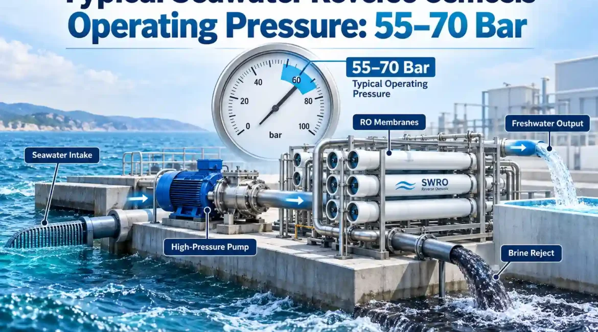
A typical seawater reverse osmosis operating pressure is about 55–70 bar, or roughly 800–1,015 psi. That range is a practical engineering reference, not a fixed setpoint. Actual SWRO feed pressure depends on seawater salinity, temperature, membrane permeability, recovery rate, membrane age, feed-channel pressure loss, permeate backpressure, and the product-water target. A 60-bar system may be perfectly reasonable under one design condition and inadequate under another.
For equipment selection, I’d treat 55–70 bar as the normal conversation range for conventional first-pass seawater RO, then calculate the required pressure from the actual feed analysis and membrane design. The most expensive mistake is not choosing 60 instead of 65 bar. It is designing the pump, pressure vessels, energy-recovery device, piping, controls, and pretreatment around an assumed pressure without defining the conditions that produced it.
55–70 Bar Is the Right Starting Range, but It Is Not the Design Answer
The 55–70 bar figure has a sound technical basis. A Department of Energy and NREL desalination report states that seawater reverse osmosis commonly requires about 800–1,000 psi, or 55–69 bar, to overcome osmotic pressure and drive water through the membrane. The report also explains why high-pressure pumping is such an important part of desalination economics.
That is the number I would use when someone needs a quick estimate, an early pump-envelope discussion, or a preliminary equipment budget. I would not use it as the final operating pressure on a purchase specification.
There are three different questions that often get compressed into the same pressure number:
- What pressure is normally seen in SWRO? About 55–70 bar is a defensible general answer.
- What pressure will this specific plant require? That must be calculated from feedwater, temperature, recovery, membrane selection, flux, pressure losses, and permeate conditions.
- What pressure should the equipment be rated for? Equipment design pressure must include the operating envelope, transients, control strategy, membrane limits, pump shutoff behavior, and the applicable mechanical design requirements. It should not simply equal normal operating pressure.
I see many poor specifications because those three values are treated as interchangeable. They are not.
| Pressure reference | Typical value or meaning | What a buyer should use it for |
|---|---|---|
| 55 bar | About 798 psi / 5.5 MPa | Lower end of conventional SWRO operation under favorable design conditions |
| 60 bar | About 870 psi / 6.0 MPa | Reasonable preliminary reference for many normal-salinity SWRO discussions |
| 65 bar | About 943 psi / 6.5 MPa | Common engineering territory when temperature, recovery, flux, or salinity increases pressure demand |
| 70 bar | About 1,015 psi / 7.0 MPa | Upper end of the frequently quoted conventional range; verify the reason pressure is this high |
| Above 70 bar | Application-dependent | Review salinity, temperature, recovery, concentrate osmotic pressure, membrane selection, fouling, and high-pressure equipment limits before treating it as normal |
These values are operating references rather than equipment pressure ratings or project guarantees.
Why Seawater RO Needs Much More Pressure Than Ordinary RO
Reverse osmosis is a pressure-driven separation process. Seawater naturally creates osmotic pressure because one side of the membrane contains a high concentration of dissolved salts. The RO pump has to create enough hydraulic pressure to overcome that osmotic pressure and still leave enough net driving pressure to produce the required permeate flow.
A simplified way to think about the process is:
Net Driving Pressure ≈ Average Feed-Side Hydraulic Pressure − Permeate Pressure − Average Osmotic Pressure Difference
The equation looks simple, but each part moves during operation.
Feed salinity changes osmotic pressure. Recovery changes the concentration on the reject side. Water temperature changes membrane permeability. Fouling adds resistance. Feed spacers create hydraulic pressure drop. Permeate piping can add backpressure. Membrane aging changes performance. That is why a membrane train does not have one universal pressure requirement independent of operating conditions.
Osmotic pressure is the first pressure you have to overcome
Normal seawater contains enough dissolved salt to create substantial osmotic pressure before the RO system produces a single gallon of permeate. As water passes through the membrane, salt remains primarily in the concentrate stream. The remaining feed therefore becomes saltier as it travels through the pressure vessel.
This distinction matters. The membrane elements near the tail end of a vessel are not seeing the same water concentration as the first element. Higher concentrate salinity means higher local osmotic pressure and less available driving force.
That is one reason I would never judge an SWRO design from feed TDS and pump discharge pressure alone. A useful design also needs the recovery, element arrangement, feed flow, flux, temperature, salt passage target, and predicted concentrate composition.
Applied pressure must exceed osmotic pressure by a useful margin
If applied pressure merely equals the osmotic pressure difference, useful permeate production approaches zero. The system needs additional pressure to create membrane flux and overcome hydraulic losses.
Increasing pressure generally increases permeate production within the membrane operating envelope, but more pressure is not automatically better. Higher pressure increases pump energy, mechanical loading, and potentially membrane compaction. It can also hide an operational problem if operators continuously increase pressure to compensate for fouling.
I’d prefer a plant that produces the specified flow at a justified normalized pressure over a plant that simply has a bigger pump.
What Actually Determines SWRO Feed Pressure?
If a supplier gives one pressure number before asking about feedwater, I would treat that number as a budget estimate rather than a process design. The following variables explain most of the pressure movement seen in seawater reverse osmosis.
1. Feedwater salinity
Salinity is one of the strongest drivers of SWRO feed pressure. As dissolved-salt concentration rises, osmotic pressure rises. More hydraulic pressure is then required to maintain the same membrane production.
This is why a high-salinity feed should not automatically be treated as ordinary seawater just because both sources are described as “salt water.” RO concentrate, process brine, and naturally concentrated seawater can move outside the usual 55–70 bar design window.
For this comparison, I’m prioritizing ionic composition as well as TDS. Total dissolved solids is useful for initial screening, but scaling behavior depends on the individual ions. Two waters with similar TDS can create different limitations because calcium, sulfate, carbonate, silica, barium, strontium, and other constituents concentrate differently.
2. Feed temperature
Cold water is harder to push through an RO membrane. Water viscosity rises as temperature falls, while membrane water permeability decreases. If the plant tries to maintain the same permeate output in colder feedwater, required pressure normally rises.
Warm water behaves in the opposite direction: membrane productivity increases, so less hydraulic pressure may be needed for the same permeate flow. The tradeoff is that salt passage also tends to increase with temperature, which can affect product-water quality.
A specification that says only “60 bar operating pressure” is therefore incomplete. I’d want to know the temperature associated with that number and the minimum design temperature used for pump sizing.
3. Recovery rate
Recovery is the portion of RO feed converted to permeate:
Recovery (%) = Permeate Flow ÷ Feed Flow × 100
As recovery rises, more water is removed while most salt stays in the concentrate. Concentrate salinity therefore increases. The system has to work against higher osmotic pressure, especially toward the concentrate end of the membrane train.
A Bureau of Reclamation technical report discussing seawater system design describes 40–50% recovery as a practical range in the seawater configuration considered in that work. The same report emphasizes recovering hydraulic energy from the concentrate rather than simply discarding that pressure.
I would not turn 40–50% into a universal guarantee. Intake quality, pretreatment, membrane selection, scaling risk, boron or salt-rejection requirements, temperature, energy economics, and concentrate management can all shift the preferred recovery.
4. Membrane flux
Flux describes how much permeate is produced per unit of membrane area. Higher design flux allows a given production rate with less membrane area, but it places more demand on the membrane surface.
That can increase required net driving pressure and worsen concentration polarization. It can also make fouling consequences appear faster.
If I were choosing between two proposals with the same capacity, I would compare membrane area and design flux before comparing pump motor size. A lower-capital design can look efficient on a quotation while quietly asking every membrane element to work harder.
5. Membrane permeability and membrane condition
New membrane elements have defined water permeability and salt rejection under reference test conditions. Real operation is different. Membrane performance changes with temperature, pressure history, fouling, scaling, oxidation exposure, cleaning history, and normal aging.
If normalized permeate flow declines, operators sometimes compensate by increasing pressure. That may restore production temporarily, but the pressure increase is a symptom, not a repair.
I’d recommend trending normalized performance before changing operating pressure. Raw pressure alone cannot tell you whether the membrane has actually deteriorated because temperature and feed salinity may have changed at the same time.
6. Feed-channel pressure drop
Pressure is lost as feedwater moves through membrane feed spacers, pressure vessels, headers, valves, fittings, cartridge filters, and associated piping. Some pressure loss is unavoidable.
A rising differential pressure across the membrane train is different from a uniform change in feed pressure. Increasing differential pressure often points toward feed-channel fouling, suspended solids, biological growth, scale deposition, or another hydraulic restriction.
The operating team should therefore monitor both absolute pressure and differential pressure.
7. Permeate backpressure
Permeate is normally kept at relatively low pressure, but it is not always at zero gauge pressure. Long piping runs, control valves, elevated tanks, downstream membranes, or other process requirements can create permeate backpressure.
Every additional bar on the permeate side reduces effective membrane driving pressure by roughly the same hydraulic amount. A design that ignores permeate backpressure can therefore underpredict the required feed pressure.
8. Product-water specification
A plant designed only to reduce salinity does not necessarily have the same arrangement as a system designed for very low finished-water TDS, specific boron control, or demanding industrial reuse.
A second RO pass may be added after the first SWRO pass. That second pass treats already-desalinated water, so its operating pressure is much lower than first-pass seawater pressure. The first-pass design still has to provide enough permeate quantity and quality for the downstream process.
A Practical Pressure Selection Matrix
The table below is how I would use the 55–70 bar range during preliminary discussion. These are screening judgments, not membrane-design guarantees. Final pressure must come from project-specific membrane calculations using the selected element and defined feed conditions.
| Operating condition | Expected pressure tendency | What I would check before selecting the pump |
|---|---|---|
| Normal seawater salinity, moderate temperature, conservative recovery | Lower to middle portion of the 55–70 bar range may be practical | Minimum temperature, target flux, membrane area, pressure losses, product TDS |
| Normal salinity with colder feedwater | Pressure requirement rises | Winter or minimum feed temperature and required production at that condition |
| Higher feed salinity | Pressure requirement rises | Full ion analysis, osmotic pressure, concentrate salinity, membrane and vessel pressure limits |
| Higher recovery target | Tail-end osmotic pressure rises | Scaling projection, concentrate chemistry, element flux distribution, ERD operating point |
| Higher design flux | More net driving pressure may be required | Membrane area, fouling risk, pretreatment quality, long-term normalized performance |
| Fouled or aged membrane train | Operating pressure may creep upward | Normalized permeate flow, differential pressure, cleaning history, salt passage |
| Higher permeate backpressure | Feed pressure must compensate | Downstream piping, elevation, valves, second-pass interface |
| Feed significantly more concentrated than ordinary seawater | May move beyond the conventional 55–70 bar envelope | Whether conventional spiral-wound SWRO remains the right process at all |
55 Bar vs. 60 Bar vs. 70 Bar: What Changes Commercially?
Pressure affects much more than the membrane skid. As design pressure increases, equipment selection changes throughout the high-pressure section.
At about 55 bar
A system operating near 55 bar is working near the lower end of the standard SWRO range. I would first confirm why the pressure can be this low. Favorable temperature, moderate salinity, conservative flux, lower recovery, highly permeable membrane elements, low permeate backpressure, or a combination of those conditions may explain it.
If a supplier promises full output at 55 bar but provides no design temperature and no feed analysis, the number has limited purchasing value.
At about 60–65 bar
This is a useful preliminary design neighborhood for many conventional seawater systems. Pump selection, pressure vessels, high-pressure piping, valves, instruments, and an energy-recovery device can usually be discussed meaningfully once the feed envelope is known.
I’d still require performance calculations at the minimum expected temperature and maximum expected salinity. The average operating day is rarely the condition that determines the required pump head.
At about 70 bar
Seventy bar is still within the widely cited SWRO operating range, but I would ask what is driving the system toward the upper end. High salinity, cold feedwater, high recovery, aggressive flux, hydraulic losses, permeate backpressure, or membrane condition may be responsible.
A high number is not automatically a bad design. An unexplained high number is.
Above the normal SWRO range
Once the process moves materially above conventional seawater pressure, I’d stop treating the problem as a routine pressure adjustment. High osmotic pressure can make the economics and mechanical design substantially different.
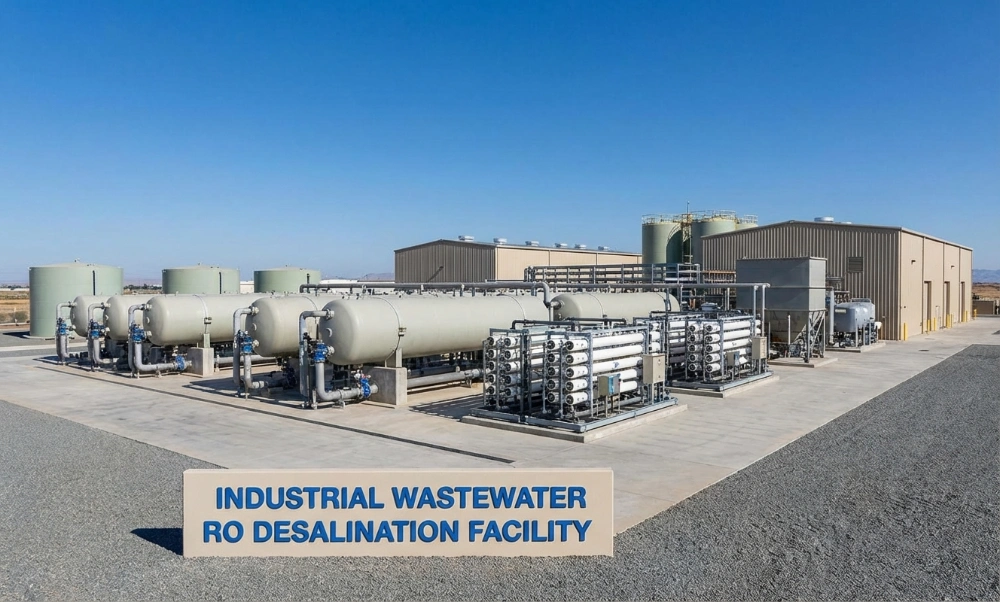
This is also where it becomes useful to distinguish standard seawater desalination from high-salinity industrial concentration. Memva describes DTRO membrane systems for high-TDS wastewater as a separate high-pressure membrane approach for difficult, fouling-prone, or concentrated streams. DTRO is not a substitute for conventional SWRO in every case; the comparison matters because high-salinity wastewater and seawater are different feed problems even when both require high pressure.
Pressure and Energy Consumption Are Closely Connected
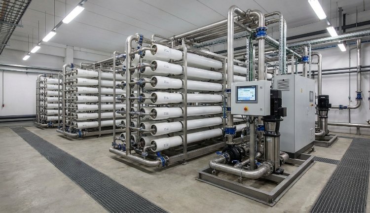
Pressure is expensive because pressure requires pumping power. The hydraulic relationship is straightforward: more flow at more pressure requires more power.
A convenient preliminary pump equation is:
Pump shaft power (kW) ≈ Flow (m³/h) × Pressure rise (bar) ÷ [36 × Pump efficiency]
Consider a simplified example with 100 m³/h entering a high-pressure pump at a 60-bar pressure rise and 85% pump efficiency:
100 × 60 ÷ (36 × 0.85) ≈ 196 kW
If that system recovers 45% of the feed as permeate, production would be 45 m³/h. Without useful recovery of reject pressure, the high-pressure pump alone would represent roughly:
196 kW ÷ 45 m³/h ≈ 4.36 kWh/m³ of product
That simplified calculation is exactly why an energy recovery device matters in SWRO. A large fraction of the feed leaves the membrane train as concentrate while still carrying substantial hydraulic pressure. Throwing that pressure away forces the pump and motor to replace energy that could otherwise be transferred back to the incoming seawater.
A 2024 paper published in Joule reviewed data from 39 facilities and reports current SWRO specific energy consumption in the broad range of about 2.5–4.0 kWh/m³. The study identifies efficient pumps, energy-recovery devices, membrane performance, operating flux, and system configuration as major areas affecting energy demand.
That 2.5–4.0 kWh/m³ range should not be used as a guaranteed plant figure. Intake pumping, pretreatment, first-pass RO, second-pass treatment, remineralization or polishing, product pumping, and concentrate handling can all change the plant boundary used for the calculation.
Pressure optimization should be measured against normalized production
Reducing pressure is not an energy-saving achievement if permeate output falls by the same proportion. The useful metric is energy per unit of acceptable product water, not pump pressure by itself.
For the same reason, increasing recovery is not automatically an economic improvement. Higher recovery reduces feed and concentrate flow per unit of product, but it raises concentration and can increase pressure, scaling risk, cleaning frequency, or membrane stress.
I’d compare the complete operating point rather than chase one KPI.
A small efficiency difference becomes meaningful at continuous production
Suppose an engineering change reduces specific electricity consumption by 0.10 kWh for every cubic meter of product water. At 10,000 m³/day and an assumed electricity price of $0.10/kWh, the arithmetic is:
0.10 kWh/m³ × 10,000 m³/day × 365 days × $0.10/kWh = $36,500 per year
That is not a market-price claim or a guaranteed saving. It is a simple way to evaluate why pump efficiency, ERD performance, membrane flux, pressure losses, and control strategy deserve attention during procurement rather than after commissioning.
How an Energy Recovery Device Changes the Pumping Arrangement
In a conventional SWRO train without energy recovery, the high-pressure pump has to supply pressure to essentially the full membrane feed flow. The concentrate then passes through a pressure-reducing device and loses most of its remaining hydraulic energy.
Modern designs recover much of that concentrate pressure.
With an isobaric pressure-exchange arrangement, high-pressure concentrate transfers pressure directly to a portion of incoming seawater. The main high-pressure pump therefore does not need to provide the entire pressure duty to the entire feed flow in the same way as a simple throttling arrangement.
The exact hydraulic architecture varies by equipment supplier, system size, control concept, and operating range. During equipment review, I’d ask for more than the statement “energy recovery included.”
- What type of ERD is proposed?
- What design feed flow and concentrate flow define its operating point?
- What efficiency is guaranteed at the specified condition?
- How does performance change during turndown?
- Is a booster pump required?
- What mixing or leakage is included in the membrane calculation?
- How will the PLC coordinate the high-pressure pump, booster pump, ERD, and control valves during startup and shutdown?
- What bypass arrangement is provided for commissioning and maintenance?
For a commercial SWRO project, those answers are usually more valuable than another decimal place on nominal membrane salt rejection.
High-Pressure Pump Selection: What I Would Specify
The pump is one of the most consequential components in an SWRO plant because it sits directly between process requirements and electricity consumption.
I would not purchase it from rated pressure alone.
Define the operating envelope, not one duty point
The pump schedule should state at least:
- minimum, normal, and maximum feed flow;
- minimum, normal, and maximum required discharge pressure;
- minimum and maximum feed temperature;
- expected salinity range;
- normal recovery range;
- suction-pressure conditions;
- required turndown;
- motor rating and efficiency basis;
- variable-frequency-drive requirements;
- materials for wetted components;
- allowable vibration and noise requirements where relevant;
- instrumentation and protection logic;
- pump efficiency at the actual design point rather than only at best efficiency point.
A bigger motor does not solve a weak hydraulic design
Oversizing is often defended as “safety margin.” Some margin is necessary. Excessive margin creates a different problem: the pump may spend years operating away from its efficient zone while the plant throttles away unnecessary head.
If extra pressure capacity is required for cold water, membrane aging, or an unusual salinity event, I’d want that requirement documented. Then the VFD and control system can operate efficiently during normal conditions while preserving the required high-pressure capability.
Check the pump against the membrane pressure limit
The pump, motor, VFD, control valve, and pressure-relief strategy have to be coordinated with the maximum allowable membrane-element and pressure-vessel conditions.
A pump may be physically capable of producing more pressure than the membrane train should ever see. A closed downstream valve, incorrect VFD command, failed transmitter, or poorly designed startup sequence can therefore create an overpressure event even if normal operation is only 60 or 65 bar.
The protection philosophy needs to be designed, not assumed.
Pressure Vessel and Piping Ratings Must Not Equal the Normal Operating Pressure
If a plant normally runs at 65 bar, selecting every high-pressure component with a 65-bar rating is not a sound specification.
Normal operating pressure, maximum operating pressure, design pressure, test pressure, and component maximum allowable working pressure are different concepts. The correct values depend on the mechanical code, component type, temperature, pump shutoff behavior, transient conditions, safety devices, and project requirements.
I’d ask the supplier to provide a pressure schedule identifying:
| Местоположение | Pressure information I would request | Why it matters |
|---|---|---|
| High-pressure pump suction | Minimum and normal suction pressure | Confirms NPSH margin and cavitation risk |
| High-pressure pump discharge | Normal, maximum operating, and maximum possible pressure | Defines the highest hydraulic duty |
| RO feed header | Normal pressure and transient allowance | Protects pressure vessels, piping, and instruments |
| RO concentrate header | Expected pressure after membrane pressure drop | Required for ERD and concentrate piping design |
| ERD high-pressure connections | Operating range and component rating | Critical for energy recovery and transient management |
| Permeate header | Normal and maximum backpressure | Directly affects net driving pressure |
Materials Matter at 60 Bar Because Seawater Is Corrosive
Pressure gets most of the attention, but chloride exposure can be just as important to equipment life. Material selection has to consider chloride concentration, temperature, oxygen content, fabrication method, crevices, welding quality, chemical-cleaning exposure, and mechanical stress.
High-pressure SWRO components are frequently manufactured from corrosion-resistant alloys or suitable nonmetallic materials depending on the component and duty. Duplex or super-duplex stainless grades are commonly evaluated for demanding high-pressure seawater service, while engineered plastics and composites may be practical elsewhere in the plant.
I would not approve a material merely because the quotation says “stainless steel.” The grade, product form, weld procedure, surface condition, and actual service environment matter.
The supplier should identify the wetted material for the high-pressure pump, piping, fittings, valves, fasteners where relevant, instrumentation connections, pressure vessels, and chemical-injection points.
Pretreatment Determines Whether 60 Bar Stays 60 Bar
A clean membrane train and a fouled membrane train can require very different pressures to produce the same flow. This is why the pretreatment section of an SWRO project deserves the same design discipline as the high-pressure skid.
Depending on the intake and water quality, pretreatment can include screening, clarification or dissolved-air flotation, media filtration, ultrafiltration, cartridge filtration, chemical conditioning, dechlorination, pH adjustment, antiscalant dosing, or other processes.
The correct train depends on suspended solids, algae, organics, biological activity, oil, turbidity, seasonal variation, and membrane requirements.
Do not treat SDI as the only pretreatment metric
Silt Density Index is useful, but it does not describe every fouling mechanism. A low-SDI feed may still contain organics or biological material that affects long-term operation.
The Bureau of Reclamation report cited later in this article used a conceptual pretreatment basis below 0.1 NTU turbidity and below SDI 3 for a particular design. I would treat those numbers as an example of a conservative project basis, not as a universal requirement for every membrane system.
The selected membrane supplier’s operating and warranty limits should control the final specification.
How Pressure Should Change During Startup
A seawater RO unit should not normally go from zero to full operating pressure as fast as the pump can accelerate.
Startup control should establish adequate feed flow, remove air, confirm valve positions, stabilize pretreatment supply, and then raise membrane pressure in a controlled manner according to the selected membrane and system procedures.
The exact ramp rate belongs in the commissioning documentation. Sudden pressure changes can create hydraulic shock, telescope membrane elements, damage seals, or upset the ERD and pump controls.
I’d want the PLC sequence to define:
- low-pressure flushing before high-pressure operation;
- permissives for feed flow and tank levels;
- high-pressure pump start conditions;
- VFD ramp behavior;
- ERD and booster-pump coordination;
- high-pressure and high-high-pressure trips;
- permeate diversion during unstable startup quality;
- shutdown depressurization;
- freshwater or permeate flushing where the process design requires it.
How to Diagnose an SWRO System That Needs More Pressure Than Before
A rising pressure trend deserves investigation. The correct question is not simply “How much more pressure can the pump provide?”
The better question is “What changed?”
| Observed change | Possible causes to investigate | What I would review first |
|---|---|---|
| Feed pressure rises while normalized permeate flow falls | Membrane fouling, scaling, permeability loss | Normalized flow, cleaning history, feed chemistry, pretreatment performance |
| Differential pressure rises strongly across vessels | Feed-channel fouling, solids, biological growth, scale | Pressure profile by array, cartridge filter condition, SDI/turbidity trend, biological indicators |
| Pressure rises but water has become colder | Normal temperature effect may explain part of the change | Temperature-normalized membrane performance |
| Pressure rises with higher feed conductivity | Higher osmotic pressure | Feed TDS, conductivity, full analysis if composition changed |
| Permeate conductivity rises sharply with little pressure change | Membrane damage, seal problem, element issue, feed change | Pressure-vessel probing, salt passage, O-ring and element condition |
| Pressure and flow fluctuate | Pump suction issue, cavitation, VFD instability, ERD instability, air entrainment, valve behavior | Suction pressure, tank level, pump current, vibration, ERD data, control-loop trend |
| Higher pressure required shortly after cleaning | Incomplete cleaning, irreversible fouling, scaling, incorrect cleaning chemistry, membrane aging | Before/after normalized performance and cleaning records |
Normalize before deciding the membrane is fouled
Raw permeate flow and pressure are strongly affected by feed temperature, salinity, and operating recovery. Normalization converts operating data toward a reference condition so the team can see whether membrane performance itself is deteriorating.
I’d recommend trending at least feed pressure, concentrate pressure, permeate pressure, feed flow, concentrate flow, permeate flow, feed conductivity, permeate conductivity, temperature, differential pressure, recovery, and normalized permeate performance.
A spreadsheet can work on a small plant. A historian or SCADA trend is better when the system operates continuously.
Do Not Use Pressure Alone to Decide When to Clean RO Membranes
CIP timing should be based on changes in normalized performance and membrane-supplier guidance rather than an arbitrary calendar interval.
Cleaning too late can allow deposits to become more difficult to remove. Cleaning unnecessarily exposes membranes to chemical and operational stress.
The operating team should watch for a combination of normalized permeate-flow decline, increased normalized salt passage, and increased differential pressure. The exact trigger values should follow the membrane supplier’s technical limits and the plant’s validated operating procedure.
The chemistry also matters. Carbonate scale, sulfate scale, metal hydroxides, silica, biological fouling, and organic fouling are not the same deposit. A cleaning solution that works for one can be ineffective or damaging for another.
SWRO Pressure Compared With Other RO Duties
Not every reverse osmosis system is a 60-bar system. Feed salinity determines much of the difference.
| RO duty | General pressure character | Main engineering limitation |
|---|---|---|
| Low-TDS process or potable-water RO | Much lower than SWRO | Flux, product quality, fouling, scaling |
| Brackish-water RO | Normally well below seawater pressure | Recovery and scaling often become more important than extreme pressure |
| Seawater RO | Commonly about 55–70 bar | Osmotic pressure, energy use, recovery, corrosion, intake and pretreatment |
| Concentrated brine or high-TDS wastewater | Can exceed conventional SWRO pressure | High osmotic pressure, scaling, fouling, membrane limits, mechanical pressure rating |
This distinction is commercially useful. A supplier experienced with ordinary low-pressure RO is not automatically experienced with seawater desalination. Likewise, a supplier working with high-pressure industrial brine should not assume that wastewater design practices can simply be transferred to seawater intake and potable-water production.
Memva’s published RO desalination equipment overview discusses the relationship between high-pressure RO, energy recovery, membrane concentration, and downstream treatment. For difficult industrial streams rather than conventional seawater, the company also separates high-pressure membrane and evaporation equipment by process duty. I think that distinction is useful during project definition: describe the water first, then decide what equipment category actually fits it.
What a Useful SWRO Equipment Quotation Should Contain
A quotation that says “capacity: 1,000 m³/day, operating pressure: 60 bar” does not contain enough information to compare engineering quality.
I’d recommend requesting a defined design basis with the following data.
Feedwater basis
- design feed TDS and conductivity;
- full major-ion analysis;
- boron where relevant;
- pH;
- minimum, normal, and maximum temperature;
- turbidity and suspended solids;
- organic or biological fouling indicators where relevant;
- intake type and pretreatment outlet assumptions.
Membrane design
- membrane element type;
- number of elements;
- number of pressure vessels;
- elements per vessel;
- design flux;
- feed flow;
- permeate flow;
- concentrate flow;
- recovery;
- predicted feed and concentrate pressure;
- predicted permeate TDS under defined conditions;
- minimum-temperature performance;
- maximum-salinity performance.
Mechanical and electrical scope
- high-pressure pump duty and efficiency;
- motor rating;
- VFD;
- energy-recovery device type and rated performance;
- booster pump where applicable;
- pressure-vessel rating;
- high-pressure piping material;
- valve materials and pressure class;
- pressure transmitters and switches;
- conductivity meters;
- flowmeters;
- PLC and HMI;
- alarm and shutdown philosophy;
- CIP system;
- flushing system;
- chemical dosing systems;
- instrument-air or utility requirements where applicable.
Performance guarantees
The guarantee should state the conditions under which it applies. Product-water flow and quality without feed salinity, temperature, feed pressure, recovery, membrane condition, and pretreatment assumptions are incomplete guarantees.
If I were comparing suppliers, I’d rank a transparent design basis above a more attractive headline recovery number.
Pressure Is Only One Part of Lifecycle Cost
Procurement teams naturally focus on equipment price, but an SWRO system is a continuous process asset. Electricity, membrane replacement, pretreatment chemicals, cartridge filters, cleaning chemicals, spare parts, maintenance labor, intake operation, concentrate management, and downtime can dominate the economics over time.
Pressure affects several of those costs at once.
A poorly optimized membrane design may use less membrane area but require higher flux and pressure. A cheap pump may consume more electricity. An ERD selected too far from its best operating point may underperform. Weak pretreatment can increase cleaning and membrane replacement. Inadequate corrosion resistance can create maintenance problems unrelated to membrane performance.
That is why I’d compare quotations on a lifecycle basis rather than treating the membrane skid as a collection of commodity parts.
| Commercial question | Data to request | Reason it affects lifecycle cost |
|---|---|---|
| How much pressure does the plant need? | Calculated pressure at defined temperature, salinity, recovery, and flux | Drives pump and energy requirements |
| How efficiently is that pressure generated? | Pump efficiency at duty point and motor efficiency | Direct electricity impact |
| How much reject pressure is recovered? | ERD performance at normal and turndown conditions | Can materially reduce high-pressure pumping demand |
| How hard are the membranes being driven? | Design flux and membrane area | Affects pressure, fouling sensitivity, and replacement economics |
| How stable is pretreatment? | Guaranteed pretreatment outlet and monitoring plan | Affects membrane fouling and cleaning frequency |
| What happens at the worst feed condition? | Cold-temperature and high-salinity design cases | Determines whether production can be maintained year-round |
| What happens when one train is offline? | Redundancy and operating philosophy | Determines real plant availability |
What I Would Ask a Seawater RO Manufacturer Before Ordering
The quality of the supplier’s questions is often as revealing as the quotation itself.
A technically serious manufacturer should ask for water analysis, flow, operating schedule, temperature range, product-water target, recovery expectations, intake information, electrical supply, site utility constraints, and concentrate-disposal plan before finalizing the design.
I’d ask the supplier these questions in return:
- What exact feed salinity and temperature produce the quoted operating pressure?
- What happens to required pressure at the minimum feed temperature?
- What recovery is assumed?
- What is the membrane flux?
- What concentrate TDS is predicted?
- What feed-channel pressure drop is expected when the elements are clean?
- How is membrane fouling detected?
- What is the pump efficiency at the actual operating point?
- How is reject pressure recovered?
- What happens to ERD efficiency at reduced flow?
- What is the maximum pressure the pump can generate?
- How is the membrane train protected against overpressure?
- Which high-pressure wetted materials are specified?
- What pretreatment outlet quality is required?
- What performance is guaranteed, and under exactly what feed conditions?
- How are commissioning, membrane loading, startup, flushing, and CIP handled?
Memva describes its project approach as beginning with water chemistry and treatment objectives rather than a fixed model number. The same principle is relevant to SWRO procurement. The company’s engineering and manufacturing overview provides additional context on how water analysis, pressure, materials, membrane treatment, and downstream concentration are considered in equipment selection.
A Better Way to Write the Pressure Requirement in a Purchase Specification
I would avoid a specification that says only:
“RO operating pressure: 60 bar.”
A more useful engineering requirement would read conceptually like this:
The membrane system shall produce the specified permeate flow and quality over the defined feed salinity and temperature range. The supplier shall calculate normal and maximum required feed pressure using the proposed membrane elements, recovery, flux, pressure losses, and permeate backpressure. The high-pressure pump, energy-recovery device, pressure vessels, piping, valves, instrumentation, and protection logic shall be selected for the complete operating and transient pressure envelope.
That wording prevents a common procurement failure: forcing every supplier to quote the same arbitrary pressure even though their membrane area, pump efficiency, ERD arrangement, and hydraulic design may be different.
My Practical Judgment on the 55–70 Bar Rule
I’d keep the 55–70 bar range. It is useful, technically defensible, and easy for buyers and engineers to communicate. The mistake is treating the range as a design specification rather than a reference.
If I were reviewing a conventional SWRO proposal, I would expect the calculated first-pass operating pressure to make sense somewhere around this range under normal seawater conditions. If it is materially lower, I would ask which favorable assumptions make that possible. If it is near or above the upper end, I would ask which design condition is driving the pressure upward.
The strongest proposal is not automatically the one with the lowest pressure. It is the one that explains the pressure, demonstrates the membrane operating point, identifies the worst-case condition, recovers reject energy efficiently, protects the equipment from transients, and states performance guarantees against a clear feedwater basis.
Часто задаваемые вопросы
What is the typical operating pressure for seawater reverse osmosis?
A conventional first-pass seawater RO system commonly operates at approximately 55–70 bar, or about 800–1,015 psi. A Department of Energy/NREL technical report gives approximately 800–1,000 psi, equivalent to about 55–69 bar, as a representative seawater RO pressure range. Actual pressure depends on salinity, temperature, recovery, membrane selection, flux, pressure loss, and permeate backpressure.
Is 60 bar enough for seawater RO?
It can be. Sixty bar falls within the normal SWRO operating range, but no supplier should guarantee production from pressure alone. A 60-bar design must still be checked at the required feed salinity, minimum temperature, recovery, membrane flux, and product-water specification. Colder or more saline water may require more pressure.
Why does SWRO sometimes operate near 70 bar?
Higher pressure may be required because of increased feed salinity, low water temperature, higher recovery, higher membrane flux, permeate backpressure, pressure losses, or declining membrane permeability. A plant operating near 70 bar is not necessarily abnormal, but the design calculation should explain the reason.
Does higher pressure always increase RO water production?
Higher net driving pressure normally increases membrane water flux within the allowed operating envelope, but continually raising pressure is not a good control strategy. More pressure consumes more energy and can conceal fouling or membrane-performance decline. The plant should evaluate normalized permeate flow, salt passage, differential pressure, temperature, and feed salinity before increasing the setpoint.
What recovery rate is typical for seawater RO?
Recovery is project-specific. A Bureau of Reclamation design discussion identifies roughly 40–50% as an economical seawater range for the configuration evaluated in that report. Modern projects can differ because recovery depends on feed composition, membrane arrangement, energy economics, scaling risk, intake design, concentrate management, temperature, and product requirements.
How much electricity does seawater reverse osmosis use?
A 2024 Joule study reports a broad current SWRO specific-energy range of approximately 2.5–4.0 kWh/m³. The exact number depends on the system boundary and plant design. High-pressure pump efficiency, energy recovery, feed salinity, recovery, membrane flux, pretreatment, post-treatment, and water-transfer requirements can all affect total consumption.
Can an SWRO plant operate above 70 bar?
Yes, some applications can require more than 70 bar, especially with elevated salinity, cold feedwater, concentrated brine, or unusual recovery requirements. Above the conventional range, I’d verify membrane-element limits, pressure-vessel ratings, pump capability, piping design, ERD suitability, concentrate osmotic pressure, and whether conventional SWRO is still the appropriate process.
What information should be sent to a manufacturer for SWRO sizing?
Send the required product-water capacity, feedwater analysis, TDS or conductivity, major ions, pH, minimum and maximum temperature, intake information, suspended-solids or turbidity data, product-water specification, expected operating hours, recovery objective, electrical supply, and concentrate-disposal conditions. The manufacturer can then calculate membrane area, recovery, feed flow, operating pressure, pump duty, and energy-recovery configuration instead of selecting equipment from capacity alone.
References and Technical Sources
- Department of Energy / National Renewable Energy Laboratory. Powering the Blue Economy: Exploring Opportunities for Marine Renewable Energy in Maritime Markets — Desalination. The report states that practical seawater RO pressure is approximately 800–1,000 psi, or 55–69 bar, and discusses the economic importance of high-pressure pumping. Просмотреть исходный код.
- Department of Energy. Desalination Basics. Provides an overview of membrane desalination and explains that higher salinity requires greater pressure to drive reverse osmosis. Просмотреть исходный код.
- Bureau of Reclamation. Variable Salinity Desalination, Desalination and Water Purification Research and Development Report No. 176. The report discusses seawater recovery, pressure requirements, energy recovery, and performance calculations. It identifies 40–50% recovery as an economical seawater range in the design case discussed and documents high-pressure RO energy-performance examples. Просмотреть исходный код.
- Alnajdi, S., Naderi Beni, A., Alsaati, A. A., Luhar, M., Childress, A. E., and Warsinger, D. M. Practical minimum energy use of seawater reverse osmosis. Joule, 2024. The study analyzes data from 39 facilities and reports current SWRO energy consumption broadly around 2.5–4.0 kWh/m³. View publication.
Technical Disclaimer
This article is intended for engineering education, preliminary equipment comparison, and project-planning purposes. Pressure ranges, recovery figures, energy values, calculations, and operating examples are not project guarantees and should not replace a site-specific process design. Final membrane selection and operating pressure must be verified against the actual feedwater analysis, temperature range, required product quality, selected membrane manufacturer’s design limits, scaling and fouling assessment, pressure-vessel and piping ratings, applicable mechanical and electrical requirements, and the project’s safety and environmental obligations. Drinking-water applications also require appropriate post-treatment, disinfection, monitoring, and compliance review before product water is placed into service.