

Semiconductor fabs generate some of the most complex industrial wastewater in manufacturing. Two parameters drive most of the design decisions: fluoride and total dissolved solids (TDS). Fluoride comes from wafer etching and cleaning steps, and it has to be removed before discharge because it attacks both biology and human health at low concentrations. TDS builds up from acids, bases, salts, and the ultrapure water rinse streams that carry them. If you’re planning a semiconductor wastewater treatment and ZLD system, the practical answer is a staged train: fluoride precipitation and polishing first, then membrane concentration, then evaporation and crystallization to close the loop on water reuse.
I’ve worked on the delivery side of these systems for over a decade, and the projects that run well share one thing — they treat fluoride and TDS as separate problems with separate unit operations, instead of trying to solve both in a single process step.
Why Semiconductor Wastewater Is Different From General Industrial Wastewater
A typical fab discharges several distinct streams, and mixing them is where a lot of designs go wrong. The main categories I see are:
- Fluoride-bearing streams from etching, cleaning, and Chemical Mechanical Planarization (CMP) — typically acidic, with fluoride in the hundreds to low thousands of mg/L range.
- Acid and base streams from wet benches and tool cleaning — low TDS individually, but they add up.
- Solvent and organic streams from photolithography and resist stripping — these need separation before biological or membrane treatment.
- Rinse water — the largest volume by far, often 60–80% of total flow, and the best candidate for reuse.
- Concentrated waste from scrubbers, exhaust treatment, and spent baths.
Because of this, a single “end-of-pipe” treatment approach rarely works. The design has to segregate at the source, treat the hard streams, and reuse the easy ones. That logic is the same whether you’re building a new fab or retrofitting an existing facility.
Fluoride Removal: Chemistry First, Equipment Second
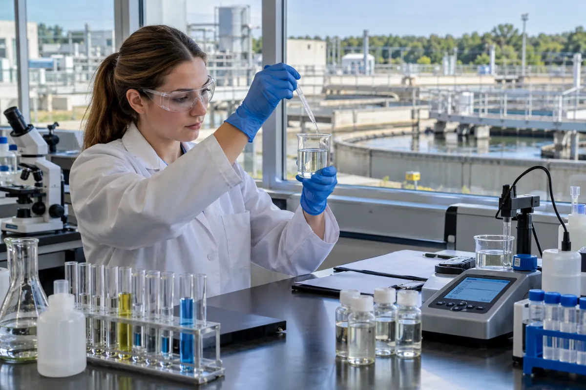
Fluoride is the parameter that fails most often in real operation. The chemistry is straightforward: add calcium, form calcium fluoride (CaF₂) precipitate, separate the solids. But the details matter enormously.
Two-Stage Precipitation
In most fab wastewater projects I’ve reviewed, a two-stage approach gives the best balance of reliability and chemical cost:
- Stage 1 — Bulk precipitation. Lime or calcium chloride is dosed at pH 10–11 to drive fluoride down from several hundred mg/L to roughly 15–25 mg/L. Sludge is separated in a clarifier or lamella settler.
- Stage 2 — Polishing. A second calcium dose, sometimes with alum or a rare-earth coagulant, brings fluoride to the 1–5 mg/L range that most discharge permits require. This stage is more sensitive to pH and mixing energy.
The single biggest operational mistake is under-dosing calcium in Stage 1 to save reagent cost. That pushes the entire burden onto Stage 2, where chemical efficiency is much lower, and you end up spending more overall.
Sludge Handling
Calcium fluoride sludge is dense and settles well, but it’s also abrasive and it holds a lot of water. A screw press sludge dewatering unit is a common choice because it handles the fine, slightly gelatinous CaF₂ solids without the blinding problems that plague plate-and-frame presses. Typical cake dryness in these applications runs 25–40%, project-dependent on feed consistency and polymer selection.
What About Fluoride That Doesn’t Settle?
Some complexes — particularly fluorosilicates and metal-fluoride complexes from CMP waste — don’t respond cleanly to simple lime precipitation. If you see residual fluoride creeping above permit after a well-run Stage 2, it’s usually a complexation issue, not a dosing issue. The fix is usually a targeted coagulant or an ion exchange polish, not more lime.
TDS Control and the Role of Membrane Concentration
Once fluoride is handled, TDS becomes the dominant design driver. Semiconductor wastewater can range from a few hundred mg/L in rinse streams up to tens of thousands in spent baths. Reverse osmosis handles the low end efficiently, but as TDS rises, standard RO hits its pressure limits and fouling becomes severe.
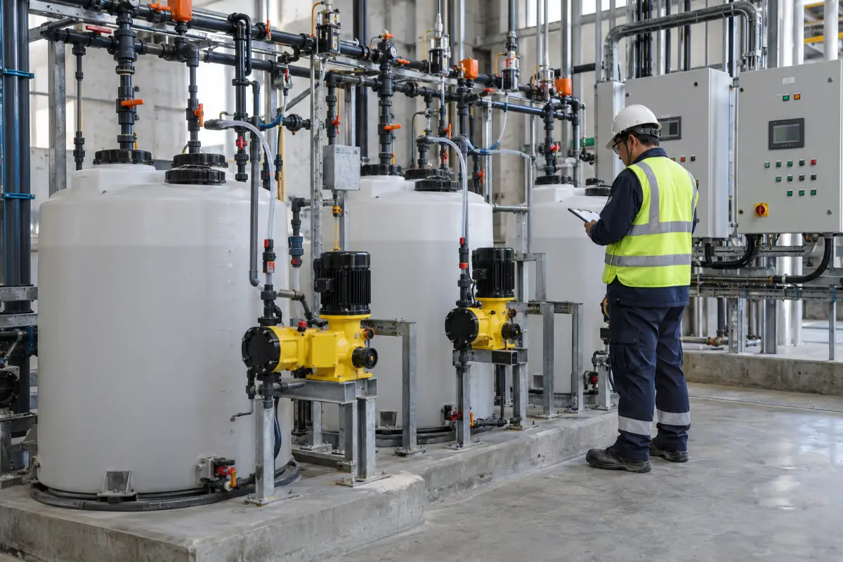
This is where high-pressure membrane systems come in. DTRO membrane systems are designed for exactly this situation — high salinity, high fouling potential, and a need for high recovery. They tolerate suspended solids better than spiral-wound RO because of the open channel design, and they can operate at pressures that standard elements can’t reach.
Typical Design Ranges for Membrane Stages
| Parameter | Standard RO | High-Pressure RO / DTRO |
|---|---|---|
| Feed TDS range | Up to ~5,000 mg/L | 5,000–35,000 mg/L |
| Operating pressure | 10–20 bar | 40–90 bar |
| Typical recovery per stage | 60–75% | 50–70% |
| Fouling tolerance | Low–moderate | Moderate–high |
| Best fit | Rinse water, low-TDS streams | Concentrate, high-salt streams |
These are indicative ranges, not guarantees. Actual numbers depend on feed chemistry, temperature, and how much pretreatment you can afford to install. I always tell clients that membrane performance is a function of what you feed it, not what the datasheet says.
Where Evaporation and ZLD Fit In
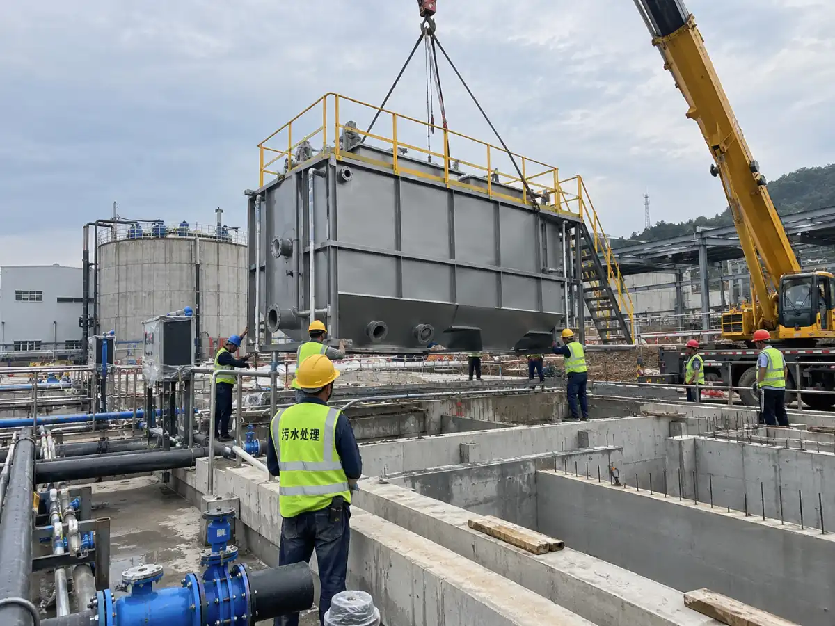
Membrane systems concentrate the brine, but they don’t eliminate it. At some point you have a stream that’s too salty for further membrane treatment, and that’s where thermal processes take over. This is the core of zero liquid discharge.
Choosing Between MVC and MVR
Mechanical Vapor Compression (MVC) and Mechanical Vapor Recompression (MVR) are the two workhorses here. The distinction is often blurred in vendor literature, but in practice:
- MVC uses a mechanical compressor to raise the pressure and temperature of the vapor, which is then reused as the heating medium. Energy consumption is typically 15–40 kWh per m³ of distillate, project-dependent.
- MVR is essentially the same principle applied at larger scale with different compressor configurations. The MVR technology approach is often preferred when flow rates are high and you want to minimize steam demand.
For semiconductor wastewater, the choice usually comes down to three factors: flow rate, required distillate quality, and whether you have waste heat available. If you have waste heat, a multi-effect evaporator can be more economical than MVC. If you don’t, MVC or MVR is almost always the better choice.
Multi-Effect vs. Single-Effect
Multiple-effect evaporators use the vapor from one effect to heat the next, which cuts steam consumption roughly in proportion to the number of effects. A double-effect evaporator uses about half the steam of a single-effect unit; a triple-effect evaporator cuts it further. But each additional effect adds capital cost, footprint, and complexity.
In semiconductor applications, I’ve seen double-effect configurations hit the sweet spot more often than triple-effect, mainly because the incremental energy savings of a third effect don’t always justify the added maintenance burden. That said, if your plant runs 24/7 and electricity prices are high, triple-effect can pay back.
Crystallization and Final Disposal
The last step in a ZLD train is crystallization. The concentrated brine is further evaporated until salts precipitate, and the solids are dewatered and sent for disposal or, in some cases, recovered. The distillate from every stage is clean enough to be reused as process water or returned to the front of the plant.
If you want a deeper look at how these stages connect, ZLD system design is worth reviewing before you commit to a layout.
Water Reuse: The Real Financial Driver
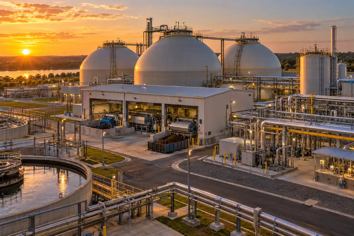
Most semiconductor fabs I’ve worked with don’t pursue ZLD because they want zero discharge — they pursue it because water reuse is cheaper than buying and treating fresh water at scale. A well-designed reuse loop can recover 70–90% of the total water volume, depending on how aggressively you segregate and treat.
The reuse strategy usually follows this hierarchy:
- Direct reuse — clean rinse water that meets quality specs goes straight back to the ultrapure water (UPW) system.
- Indirect reuse — treated water goes to cooling towers, scrubbers, or landscape irrigation.
- Deep reuse — distillate from evaporation stages is polished and returned to UPW.
The economics depend heavily on local water and discharge costs. In regions where discharge fees are high or water is scarce, the payback on a reuse system can be under three years. In regions with cheap water, it can be hard to justify on financial grounds alone — but regulatory pressure often changes that calculation.
Energy, Cost, and Lifecycle Considerations
I get asked about cost more than anything else, and the honest answer is that it varies enormously. But the structure of the cost is predictable:
| Cost Category | Typical Share of Total | Key Drivers |
|---|---|---|
| Capital (equipment) | 35–50% | Flow rate, TDS, materials of construction |
| Installation and civil | 15–25% | Site conditions, footprint, integration |
| Energy (O&M) | 20–35% | Evaporation load, electricity price |
| Chemicals (O&M) | 5–15% | Lime, polymer, antiscalant, cleaning |
| Maintenance | 5–10% | Compressor, membranes, heat exchangers |
Energy is almost always the largest operating cost in a ZLD system, and it’s dominated by the evaporation stage. This is why the choice between MVC, MVR, and multi-effect matters so much — a poorly chosen evaporator can double your operating cost over the life of the plant.
For a more detailed breakdown of what drives evaporator pricing, this analysis of MVR evaporator cost drivers covers the main variables.
Common Operational Problems and How to Avoid Them
After years of watching these systems run, I’ve seen the same failures repeat across different sites. Here’s what to watch for:
Fluoride Carryover
Usually caused by pH drift in the precipitation stage, inadequate mixing, or polymer overdose that keeps fine CaF₂ particles in suspension. The fix is better pH control and a properly sized clarifier — not more chemical.
Membrane Scaling
Calcium sulfate, silica, and calcium fluoride scale are the usual suspects. Antiscalant selection and dosing are critical, but so is the pretreatment. If you’re scaling membranes, the problem is usually upstream.
Evaporator Fouling
Heat exchanger surfaces foul with scale and organics. Regular clean-in-place (CIP) is essential, and the heat exchanger design should allow for easy access. I’ve seen systems where the heat exchanger was undersized for cleaning frequency, and the result was constant downtime.
Compressor Vibration and Wear
In MVC and MVR systems, the compressor is the heart of the process. Vibration monitoring and scheduled maintenance are not optional. A compressor failure can take the whole system down for weeks.
Foaming in the Evaporator
Semiconductor wastewater often contains surfactants and organics that cause foaming. Antifoam dosing helps, but if foaming is chronic, the upstream pretreatment isn’t removing enough organics.
Design Logic: How I’d Approach a New Project
If I were starting a semiconductor wastewater treatment and ZLD project tomorrow, here’s the sequence I’d follow:
- Characterize the waste streams. Flow, composition, variability, and peak loads. Don’t skip this — most design failures trace back to poor characterization.
- Segregate at the source. Keep fluoride, organics, and high-TDS streams separate as long as practical.
- Treat fluoride first. Two-stage precipitation with proper sludge handling.
- Concentrate with membranes. Standard RO for low-TDS streams, high-pressure or DTRO for the harder stuff.
- Evaporate and crystallize. MVC or MVR depending on scale and available heat.
- Reuse the distillate. Route clean water back to UPW or secondary uses.
The order matters. Trying to evaporate before you’ve removed fluoride and most of the TDS is a recipe for fouling and downtime. Trying to reuse water before it’s clean enough will contaminate your UPW system.
Frequently Asked Questions
How do I know if my fab needs ZLD or just discharge compliance?
It depends on your discharge permit, local water costs, and corporate sustainability targets. If your permit allows discharge at your current quality and water is cheap, ZLD may not be financially justified. But if you’re facing tightening limits, high discharge fees, or water scarcity, ZLD often pays back within a few years. The decision should be based on a lifecycle cost comparison, not just capital cost.
What’s the typical fluoride limit I need to design for?
Most discharge permits in industrialized regions set fluoride limits between 1 and 10 mg/L, with some going lower. Design for the lowest limit you can reasonably anticipate, because permits rarely get looser over time. A two-stage precipitation system with a polishing step gives you margin.
Can I use standard RO for semiconductor wastewater, or do I need high-pressure membranes?
It depends on the stream. Rinse water and low-TDS streams are fine with standard RO. High-TDS concentrates, spent baths, and streams with high fouling potential need high-pressure or DTRO membranes. Mixing the two in the same train without proper pretreatment is a common mistake.
How much does a ZLD system cost to operate?
Energy is the dominant cost, typically 20–35% of total operating expense. For an MVC-based system, expect 15–40 kWh per m³ of distillate, project-dependent. Chemicals add another 5–15%, and maintenance 5–10%. The exact number depends on your electricity price, feed composition, and how well the system is operated.
What’s the most common reason these systems fail?
In my experience, it’s inadequate waste characterization during design. When the actual wastewater doesn’t match the design basis, every downstream unit suffers. The second most common cause is poor segregation — mixing streams that should have been kept separate. Both are avoidable with proper front-end engineering.
How often do membranes and compressors need maintenance?
Membrane cleaning frequency depends on fouling rate, but typically every 1–3 months for high-fouling streams. Membrane replacement is usually every 3–5 years. Compressor maintenance is typically annual for inspection and every 3–5 years for major overhaul, depending on runtime and manufacturer recommendations.
Is water reuse realistic for a semiconductor fab, or is it just a sustainability talking point?
It’s realistic. Fabs that invest in proper segregation and treatment routinely recover 70–90% of their water. The distillate from evaporation stages is often clean enough to feed back into the UPW system after polishing. The key is designing the reuse loop from the start, not bolting it on later.
Final Thoughts
Semiconductor wastewater treatment and ZLD isn’t a single technology — it’s a sequence of them, each doing a specific job. Fluoride removal comes first because it’s the hardest to handle downstream. Membrane concentration follows, because it’s the most energy-efficient way to reduce volume. Evaporation and crystallization close the loop, and reuse turns the whole system from a cost center into a resource recovery operation.
The projects that work are the ones where the design team understood the waste streams before they sized any equipment. The ones that struggle are the ones where someone tried to shortcut that step. If you’re planning a system, spend the time on characterization and segregation — it will save you far more than it costs.