

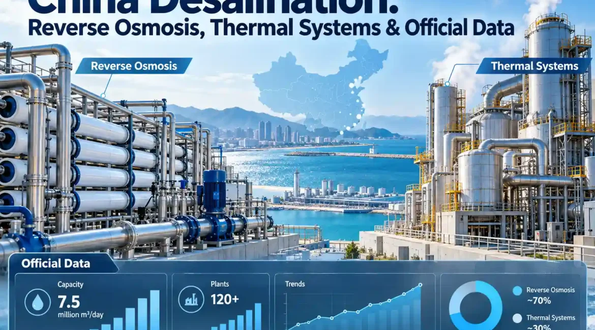
For buyers comparing China desalination equipment, reverse osmosis and thermal desalination should not be treated as interchangeable technologies. Reverse osmosis is usually the first process I’d evaluate when feed salinity, scaling risk, membrane pressure limits, and concentrate disposal allow it. Thermal treatment becomes more relevant as salinity rises, membrane recovery reaches a practical limit, or a project needs aggressive brine concentration. In difficult industrial applications, the strongest design is often a hybrid: pretreatment first, membrane recovery where it remains economical, then evaporation only for the smaller concentrate stream. The equipment decision should therefore start with water chemistry, required product-water quality, concentrate strategy, energy availability, and operating hours—not with a catalog capacity. This guide explains how I’d compare those choices, review supplier proposals, and identify the numbers that actually affect lifecycle cost.
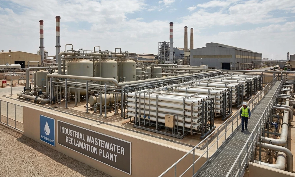
Reverse Osmosis and Thermal Desalination Solve the Same Problem Differently
Both technologies separate water from dissolved salts, but they pay for that separation in different ways. Reverse osmosis, usually shortened to RO, uses pressure. Thermal desalination uses evaporation and condensation, although the way heat is supplied and recovered varies substantially between multi-effect distillation, flash processes, and mechanical vapor recompression.
The distinction sounds simple until a procurement team starts comparing energy figures. A membrane system is normally discussed in electrical kilowatt-hours per cubic meter. A steam-driven thermal system may have both electrical consumption and a much larger thermal-energy requirement. Putting those figures in the same column without identifying the form and value of the energy can make an otherwise serious comparison meaningless.
For this comparison, I’m prioritizing five engineering questions: what the feed contains, how much water must be recovered, what happens to the concentrate, which utility is actually available at the plant, and what level of operating attention the process can realistically receive.
| Procurement question | Reverse osmosis | Thermal desalination |
|---|---|---|
| What drives separation? | Hydraulic pressure above the feedwater’s osmotic pressure | Evaporation followed by vapor condensation |
| Primary energy form | Electricity for high-pressure pumps and auxiliaries | Steam, recovered heat, or electricity for vapor compression, depending on configuration |
| What normally limits recovery? | Osmotic pressure, scaling, membrane pressure rating, fouling, and permeate-quality requirements | Scaling, corrosion, boiling-point elevation, viscosity, foaming, volatile compounds, and practical final concentration |
| Where does it usually make the most sense? | Feedwater that can be reliably pretreated and concentrated within membrane limits | High-salinity concentrate, difficult brine, or duties requiring further concentration beyond practical RO recovery |
| What residual stream remains? | Pressurized concentrate or brine | Concentrated liquid, slurry, or a stream sent to crystallization or solids separation |
| What should buyers compare first? | Feed chemistry, membrane flux, recovery, pressure, pretreatment, energy recovery, and normalized performance | Evaporation duty, heat-recovery method, boiling-point rise, metallurgy, steam/electricity demand, and final concentrate condition |
The Department of Energy makes a useful practical distinction in its desalination guidance: membrane processes such as RO generally require less overall energy than conventional thermal desalination, while thermal processes remain relevant where salinity or required treatment conditions exceed what membranes can reasonably handle.[1]
I’d use that as a starting point, not as a rule that automatically selects RO. A wastewater stream with strong calcium sulfate scaling, silica, organics, surfactants, suspended solids, or rapidly changing composition can turn a theoretically attractive membrane recovery into an unstable plant. Thermal equipment also has limits; it simply encounters a different set of them.
What the Energy Numbers Really Say
Energy consumption is one of the few desalination topics where buyers frequently receive numbers that appear precise but are not directly comparable. Before accepting any specific-energy figure, I’d ask four questions: Does it cover the complete plant or only the separation device? Is it measured at design conditions or estimated? Is thermal energy separated from electrical energy? What feed salinity, recovery, and temperature were assumed?
A 2024 review hosted by the National Renewable Energy Laboratory reported the following ranges for several desalination processes. The value of this dataset is not that every future plant will fall inside the range. Its value is that it separates thermal and electrical requirements instead of hiding them in one headline number.[2]
| Process | Application represented in the 2024 review | Thermal energy | Electrical energy | How I’d use the figure in procurement |
|---|---|---|---|---|
| Reverse osmosis | Brackish and seawater desalination | Not listed as the main energy input | 1.5–2.5 kWh/m³ for brackish water; 3–5 kWh/m³ for seawater | Use as an external reference range, then require the supplier’s project-specific estimate at stated feed conditions |
| Multi-effect distillation | Seawater desalination | 45–320 kWhth/m³ | 1.5–3 kWh/m³ | Keep thermal and electrical energy separate in the bid comparison |
| MED with thermal vapor compression | Seawater desalination | 45–128 kWhth/m³ | 8–15 kWh/m³ | Confirm the exact process boundary before comparing the quoted values with RO |
These are literature ranges, not equipment guarantees. Feed salinity, recovery, intake conditions, pump efficiency, pretreatment, pressure loss, post-treatment, operating temperature, and plant scale all influence actual electricity use.
A separate 2024 membrane-desalination roadmap reports that seawater RO represents more than 70% of installed global desalination capacity and cites approximately 3–5 kWh/m³ for current seawater RO operation, compared with a theoretical energy requirement near 1.1 kWh/m³ at 50% recovery.[3] The gap is a reminder that thermodynamic minimums are not purchasing specifications. Pumps, pressure losses, pretreatment, energy-recovery efficiency, controls, and real membrane behavior all exist between theory and the electrical meter.
Editor’s recommendation: I’d reject an energy comparison that gives one number for RO and another for thermal treatment without defining the process boundary. Ask for kWh per cubic meter of product water, operating recovery, feed TDS, feed temperature, high-pressure pump efficiency, energy-recovery assumptions, and any thermal utility separately.
How Reverse Osmosis Actually Determines Plant Performance
RO is sometimes described as filtration, but that shorthand can lead buyers in the wrong direction. The membrane is separating water from dissolved species under pressure. As the feed becomes more concentrated, its osmotic pressure increases. The high-pressure pump therefore has to provide enough pressure to overcome osmotic pressure while maintaining useful net driving pressure across the membrane.
This is why “maximum TDS” is a poor standalone specification. Two waters with the same TDS can behave very differently. Sodium chloride may dominate one stream. Another stream may contain calcium, sulfate, bicarbonate, silica, metals, organics, and compounds that create severe scaling or irreversible fouling as concentration increases.
Recovery Changes Both Economics and Chemistry
Recovery is the fraction of feed converted to permeate. If a system receives 1,000 m³/day and produces 450 m³/day of permeate, its recovery is 45%. The remaining 550 m³/day leaves the membrane stage as concentrate.
Increasing recovery sounds attractive because more water is recovered and less concentrate remains. But every increase also concentrates the rejected salts. At 50% recovery, a non-permeating constituent is theoretically concentrated to roughly twice its feed concentration before other effects are considered. At 75% recovery, the theoretical concentration factor approaches four.
That simple mass balance explains why recovery cannot be selected from a competitor’s brochure. Calcium salts, silica, barium, strontium, organics, and other constituents may become limiting long before the pressure vessel reaches its mechanical limit.
Flux Matters as Much as Membrane Quantity
Flux describes permeate production per unit membrane area. Higher design flux can reduce membrane area and equipment size, but it can also increase concentration polarization and fouling tendency. A proposal that achieves the required capacity using fewer elements is not automatically the lower-cost design over ten years.
If I were comparing two RO desalination plant quotations, I’d ask for the design flux at average and peak conditions, not just the number of membranes. I’d also request projected flux after temperature correction because colder water normally reduces membrane permeability and can increase the pressure needed for the same production rate.
Salt Rejection Is Not the Same as Finished-Water Quality
A membrane supplier may state a high nominal salt-rejection percentage under a standardized test condition. That number is useful for membrane comparison, but a complete plant has different feed chemistry, recovery, temperature, pressure, membrane age, and hydraulic staging.
The final permeate specification should therefore be expressed as measurable water-quality limits. Conductivity, TDS, boron where relevant, silica, hardness, chloride, sodium, TOC, or another process-specific parameter may matter more than a single generic rejection percentage.
For drinking-water applications, membrane permeate can also require stabilization and remineralization. World Health Organization guidance treats desalinated water as a complete water-safety problem rather than a membrane-only problem, including post-treatment, distribution-system stability, chemical hazards, and microbial risk management.[4]
Pretreatment Is Usually Where Reliable RO Plants Are Won or Lost
I think pretreatment deserves more attention in supplier comparisons than polished skid photographs do. The membrane is the expensive barrier, but feed conditioning decides what reaches that barrier every hour of the year.
For relatively stable saline water, pretreatment may include screening, coagulation where necessary, media filtration or membrane filtration, cartridge filtration, pH adjustment, antiscalant dosing, and dechlorination depending on the selected membrane chemistry.
Industrial wastewater can require substantially more. Oil separation, biological treatment, softening, metals precipitation, activated carbon, oxidation or reduction, ultrafiltration, chemical clarification, and equalization may sit upstream of RO. The correct sequence depends on the contaminants and on what they become at the planned concentration factor.
The Environmental Protection Agency notes that RO and nanofiltration commonly require pretreatment to control fouling or plugging and that the processes generate a concentrate stream containing removed salts and contaminants that still requires discharge or disposal management.[5]
That second point matters commercially. An RO plant does not eliminate salt. It separates part of the water and puts the rejected material into a smaller stream.
| Feed characteristic | Why it matters before equipment selection | Typical engineering response to evaluate |
|---|---|---|
| Suspended solids and turbidity | Can block flow channels and increase differential pressure | Clarification, filtration, ultrafiltration, cartridge filtration, or improved upstream solids separation |
| Calcium, magnesium, alkalinity, sulfate | Can create scale as recovery increases | Recovery modeling, pH control, softening, antiscalant, or limiting concentration factor |
| Silica | Can limit membrane recovery and complicate downstream concentration | Feed-specific silica evaluation, pretreatment, and conservative recovery where required |
| Oil, surfactants, and organics | May foul membranes and destabilize downstream evaporation | Source segregation, oil removal, biological or physicochemical pretreatment, adsorption, or other targeted treatment |
| Free chlorine or oxidants | May damage certain polyamide RO membranes | Oxidation-control strategy matched to the membrane supplier’s limits |
| Variable pH and conductivity | Changes scaling tendency, rejection, required pressure, and chemical dosing | Equalization, automatic dosing, alarms, interlocks, and design against the credible operating range |
| Ammonia or volatile compounds | Can affect both permeate and evaporator condensate depending on chemistry and pH | Speciation review and a treatment route designed around the required finished-water quality |
A useful equipment proposal should show where pretreatment responsibility begins and ends. If the membrane guarantee assumes SDI, turbidity, free chlorine, hardness, silica, temperature, and pH values, those conditions should appear clearly in the design basis rather than in a footnote discovered after purchase.
Where DTRO Fits Into High-Salinity and Difficult Wastewater
Conventional spiral-wound RO is widely used because it offers high membrane packing density and mature component supply. Difficult industrial feedwater can expose the limitations of its relatively tight feed-spacer geometry, particularly where suspended matter, organic fouling, precipitation, or feed variability is difficult to control.
Disc tube reverse osmosis, or DTRO, uses a different module geometry with a more open flow path. That does not make pretreatment unnecessary. It changes the hydraulic environment and can make membrane concentration practical for streams that would be troublesome for conventional spiral-wound equipment.
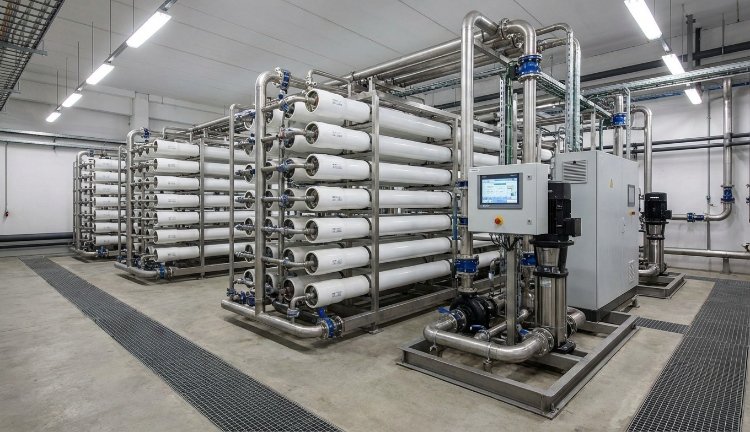
If I were choosing equipment for variable, high-TDS industrial wastewater, I’d compare the hydraulic channel design and cleaning strategy before assuming a standard spiral-wound arrangement is the lowest-cost choice. Memva’s DTRO membrane system overview is useful here because it treats pressure, TDS, recovery, and pretreatment as project-specific design parameters rather than universal guarantees.
A DTRO proposal should still answer the same fundamental questions as any other RO system:
- What feed chemistry was used in the projection?
- What operating pressure is expected at beginning-of-run and design fouling conditions?
- What is the maximum allowable pressure for every pressure-retaining component?
- What recovery is guaranteed, and under which temperature and salinity conditions?
- Which ions determine the scaling limit?
- What permeate-quality parameters are guaranteed?
- How is concentrate handled after the membrane stage?
- What normalized values will operators trend to identify fouling?
- What is the cleaning procedure, and which chemicals are compatible with the selected membrane and materials?
The important commercial distinction is not “DTRO versus RO.” DTRO is an RO configuration. The real comparison is between membrane module geometries, pressure capability, feed tolerance, membrane area, operating flux, cleanability, component availability, and lifecycle cost under the specific wastewater conditions.
Thermal Desalination Is a Family of Processes, Not One Machine
Thermal desalination is frequently discussed as though every system simply boils water. That description misses the engineering decisions that determine utility demand and equipment size.
Multi-effect distillation reuses vapor heat through a sequence of effects operating at progressively lower pressures and temperatures. Multi-stage flash uses pressure reduction to flash heated saline water into vapor across stages. Mechanical vapor recompression, often abbreviated MVR or MVC in industrial equipment discussions, mechanically compresses generated vapor so that the vapor can be reused as a heating medium.
These technologies share evaporation and condensation, but their utility profiles are very different.
Multi-Effect Systems
In a multi-effect configuration, vapor produced in one effect supplies heat to a following effect operating at a lower boiling temperature. More effects can improve steam economy, but they also require additional heat-transfer area, vessels, piping, vacuum duty, controls, and cleaning access.
I’d never select the number of effects from a simple “more stages equals higher efficiency” argument. Boiling-point elevation consumes part of the available temperature difference. Fouling adds thermal resistance. A viscous concentrate may require forced circulation. A heat-sensitive process may impose an upper temperature limit. These constraints can make an additional effect technically possible but financially unattractive.
Memva’s multi-effect evaporator engineering page gives a useful list of the design inputs that should appear in a serious quotation: evaporation duty, feed and final concentration, boiling-point elevation, viscosity, heat sensitivity, scaling tendency, volatile components, corrosion conditions, steam conditions, and the downstream treatment target.
Mechanical Vapor Recompression
MVR shifts much of the stable-operation energy demand toward electricity. Vapor generated from the liquid is mechanically compressed, which raises its pressure and saturation temperature. The recompressed vapor returns to the heat-transfer surface and provides latent heat for continued evaporation.
The compressor therefore becomes a central process component rather than a generic accessory. Vapor flow, temperature lift, compressor efficiency, turndown, entrainment control, boiling-point rise, and fouling of the heat-transfer surface all affect performance.
A universal electricity figure for MVR wastewater evaporation is not credible without those inputs. High boiling-point elevation can force a greater compressor temperature lift. Severe scaling can degrade heat transfer. Volatile organics or ammonia may alter condensate-quality requirements. Startup conditions may also require an auxiliary heat source even though normal operation recycles vapor energy.
For readers evaluating this route after membrane concentration, Memva’s MVC/MVR evaporator technical overview explains the process loop and identifies the wastewater data needed before an energy estimate can be treated seriously.
Material Selection Can Change the Entire Thermal Quote
Chloride concentration deserves special attention. A material that performs acceptably in the feed may be unsuitable after concentration, especially when temperature rises. pH, chloride, oxidizing conditions, crevice geometry, stress, and operating temperature interact.
Stainless steel grade should therefore never be selected from TDS alone. Duplex alloys, higher-alloy stainless steels, titanium, lined equipment, or other corrosion-resistant materials may be evaluated depending on the process. The right answer has to come from actual chemistry, temperature, fabrication details, and accepted corrosion-design practice.
The Hybrid RO and Thermal Route Often Has the Strongest Economics
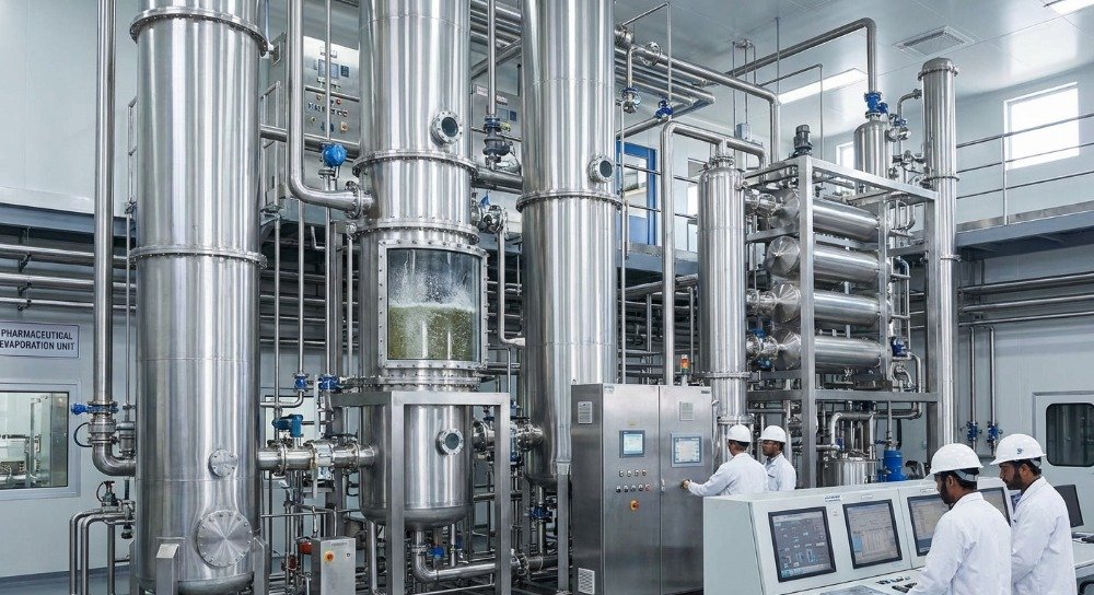
Membrane and thermal processes are frequently presented as competitors. For high-recovery industrial water systems, I see more value in asking where the handoff between them should occur.
RO is usually more energy-efficient while osmotic pressure and scaling remain manageable. Thermal evaporation is usually less sensitive to osmotic pressure but consumes considerably more energy for each cubic meter processed. The economic objective is therefore straightforward: recover water with membranes for as long as the membrane stage remains stable and economical, then send only the remaining concentrate to the thermal stage.
Consider a simplified mass balance. A plant feeds 1,000 m³/day to an RO stage operating at an assumed 50% recovery. RO produces 500 m³/day of permeate and 500 m³/day of concentrate. If the project instead sent all 1,000 m³/day directly to evaporation, the evaporator would face twice the hydraulic water-removal load before any other process difference is considered.
If a suitable membrane configuration can safely reach 70% recovery, only 300 m³/day remains for downstream management. That does not prove that 70% is feasible; the chemistry decides that. The calculation simply shows why every additional stable cubic meter recovered before evaporation can materially change downstream equipment size.
| Illustrative mass-balance item | 50% membrane recovery | 70% membrane recovery |
|---|---|---|
| Feed to membrane stage | 1,000 m³/day | 1,000 m³/day |
| RO permeate | 500 m³/day | 700 m³/day |
| Concentrate sent downstream | 500 m³/day | 300 m³/day |
| Reduction in hydraulic load sent to the next stage | Baseline | 200 m³/day less than the 50% recovery case |
| Engineering condition | Both recovery values are illustrative. Actual feasible recovery must be confirmed from osmotic pressure, scaling, membrane limits, and pretreatment. | |
The trap is pushing membrane recovery beyond the point where chemistry remains controllable. A design that saves evaporation capacity on paper but requires constant cleaning, loses normalized permeate flow, or precipitates scale inside pressure vessels is not an optimization.
Editor’s recommendation: If I were choosing for a high-salinity wastewater project with a final brine-minimization target, I’d calculate the membrane-to-thermal crossover from lifecycle cost rather than maximizing recovery in either stage. The cheapest cubic meter to evaporate is usually the one that never reaches the evaporator.
Memva’s existing RO desalination plant resource also discusses the connection between membrane concentration and downstream evaporation. I’d still require a fresh project-specific projection rather than using any general performance range as a purchase guarantee.
What I Would Send a Supplier Before Asking for a Price
A request that says “100 m³/day desalination plant, please quote” may produce a price, but it cannot produce a defensible design. Capacity tells the manufacturer how much water moves through the system. It says almost nothing about what the equipment has to separate.
If I were requesting a serious proposal, I’d send the following information before discussing the final equipment configuration.
| Information to provide | Why the supplier needs it | What should come back in the proposal |
|---|---|---|
| Average, minimum, and peak flow | Determines equipment capacity, train count, turndown, equalization, and redundancy | Design flow, train arrangement, operating hours, and turndown assumptions |
| TDS or conductivity | Provides an initial indication of salinity and required membrane pressure | Pressure range and process selection, supported by complete chemistry |
| Full major-ion analysis | Required for osmotic-pressure and scaling evaluation | Recovery basis, antiscalant or softening strategy, and concentrate chemistry |
| Calcium, magnesium, alkalinity, sulfate, silica, barium, strontium where relevant | Potential recovery-limiting scale formers | Scaling analysis and pretreatment assumptions |
| COD, TOC, oil, surfactants, solvents, ammonia | Affects fouling, biological treatment, membrane compatibility, evaporation, and condensate quality | Specific pretreatment and downstream polishing requirements |
| Suspended solids and turbidity | Influences filtration and membrane-channel selection | Feed-quality limits at the RO inlet |
| pH and temperature range | Changes membrane performance, chemistry, corrosion, and scaling | Guaranteed operating envelope |
| Required product-water quality | Defines whether one pass, two passes, remineralization, polishing, or another treatment step is required | Specific permeate or condensate guarantees |
| Concentrate disposal or final ZLD objective | Determines how aggressively water must be recovered | A complete residual-stream balance |
| Available electricity, steam, waste heat, cooling water, and space | Can change the preferred thermal configuration and plant arrangement | Utility schedule and battery-limit requirements |
| Operating hours and planned shutdowns | Influences train redundancy, storage, and annual energy calculations | Availability assumptions and maintenance philosophy |
The quality of the supplier’s questions is often more revealing than the first quotation. A manufacturer that asks only for flow and TDS is working with an incomplete picture. A manufacturer that asks about silica, hardness, sulfate, COD, temperature, peak flow, concentrate disposal, available utilities, and final water quality is at least building the right design basis.
How I’d Compare Desalination Supplier Quotations
The easiest mistake in procurement is comparing total price before normalizing scope. Two proposals that both say “500 m³/day RO system” may contain different membrane area, pump efficiency, instrumentation, pretreatment, redundancy, cleaning equipment, materials, installation boundaries, and performance guarantees.
For this comparison, I’m prioritizing what the supplier is contractually committing to rather than the quantity of features listed in the brochure.
| Bid item | What I’d request from every supplier | Why it affects the commercial decision |
|---|---|---|
| Design basis | Feed analysis, temperature, flow, recovery, operating hours, and product-water target | Without a common basis, prices are not comparable |
| Mass balance | Feed, permeate/condensate, concentrate, chemical waste, backwash, and cleaning streams | Reveals the real water recovery and residual disposal load |
| Energy estimate | Electrical load by major consumer and thermal utility separately | Allows annual operating cost to be modeled transparently |
| Membrane design | Element type, membrane area, train arrangement, flux, recovery, and design pressure | Shows whether a low capital price depends on aggressive loading |
| Energy-recovery device | Type, rated flow, pressure, efficiency assumption, and control philosophy where applicable | Can materially affect seawater RO power demand |
| Materials of construction | Material schedule for high-pressure piping, vessels, pumps, evaporator surfaces, and concentrate-contact parts | Corrosion risk increases sharply when saline streams are concentrated |
| Instrumentation | Pressure, flow, conductivity, temperature, level, differential pressure, and other required analyzers | Operators cannot manage performance that the plant does not measure |
| CIP provisions | Tank, heater if required, circulation pump, filtration, chemical compatibility, connections, and procedure | Cleaning is part of normal membrane and evaporator lifecycle management |
| Performance guarantee | Capacity, recovery, product-water quality, utility basis, and defined test conditions | Converts marketing statements into measurable acceptance criteria |
| Factory acceptance test | Mechanical, electrical, PLC, alarm, instrument, rotation, and documentation checks | Reduces preventable commissioning problems |
| Exclusions | Civil works, tanks, interconnecting pipework, cabling, chemicals, transformers, foundations, commissioning travel, and local permits | Prevents a low equipment price from becoming a high installed cost |
Where Memva Fits in a Supplier Shortlist
If I were choosing for a difficult high-TDS wastewater project rather than a simple low-salinity polishing duty, I’d put Memva in the first technical-review round because its published equipment range covers DTRO membrane concentration, MVC/MVR evaporation, and multi-effect evaporation within the same process discussion. That matters when the final solution may require a membrane-to-thermal handoff instead of a standalone machine.
I would not award a project to any manufacturer—Memva included—on website content alone. The decision should move to feed-specific calculations, process guarantees, drawings, material schedules, component data, factory testing, documentation, references applicable to the duty, and commercial terms.
That distinction protects both buyer and supplier. The manufacturer’s job is to design against an agreed operating envelope. The buyer’s job is to disclose the actual feed variability and compare proposals on the same basis.
Capital Cost Is Only One Line in the Desalination Business Case
Desalination equipment can create economic value, but calling it “profitable” without defining the avoided cost is misleading. Water recovered inside a plant may displace purchased water, reduce wastewater discharge, lower hauling volume, reduce downstream evaporator load, or support production that would otherwise face a water constraint. Those benefits are project-specific.
I’d build the business case from annual cash flows rather than from a generic payback claim.
Annual recovered-water value = recovered water volume × avoided delivered-water cost.
Annual disposal saving = reduction in externally managed concentrate or wastewater volume × actual disposal and transportation cost.
Annual energy cost = measured or guaranteed electricity consumption × operating volume × electricity tariff, plus thermal utility cost where applicable.
Annual operating cost should then include chemicals, cartridge filters, membrane replacement allowance, cleaning chemicals, labor, spare parts, compressor or pump service, analytical testing, residual disposal, and other site-specific consumables.
Simple payback = installed capital cost ÷ verified annual net savings.
The calculation is intentionally simple. Financing, depreciation, taxes, escalation, water-price risk, energy-price risk, residual value, and production impacts belong in a full financial model. A simple payback is useful for screening but should not be mistaken for a discounted cash-flow analysis.
Normalize Cost to the Same Functional Output
A low equipment price can be misleading if one proposal produces poorer water, leaves more concentrate, consumes more energy, or excludes pretreatment. The denominator matters.
If the project needs 700 m³/day of reusable water, compare systems on the installed cost and lifecycle cost of delivering that 700 m³/day at the required quality—not on nominal feed capacity.
For ZLD or near-ZLD projects, I’d also calculate the cost per cubic meter of liquid residual eliminated. That can expose a design in which inexpensive upstream equipment simply transfers too much volume to an expensive downstream evaporator.
Brine Management Must Be Designed at the Same Time as Water Recovery
Concentrate is not an afterthought. The RO stage can meet its permeate specification perfectly while the overall project fails commercially because nobody established a practical destination for the brine.
The concentrate strategy may involve permitted discharge, blending where allowed, deep disposal where appropriate and permitted, additional membrane concentration, evaporation, crystallization, resource recovery, or off-site management. The acceptable route depends on concentrate chemistry and applicable requirements.
For industrial wastewater, the concentrate can contain much more than sodium chloride. Metals, hardness, silica, refractory organics, nitrogen compounds, treatment chemicals, and process-specific contaminants may all become more concentrated.
This is another reason I’d request a complete mass balance. “90% salt rejection” describes membrane behavior; it does not describe where the rejected mass goes.
Zero Liquid Discharge Requires More Than an RO Skid
RO can substantially reduce liquid volume but does not normally convert all residual dissolved material into dry solids. As osmotic pressure and precipitation risk increase, the membrane stage reaches a practical endpoint.
A true ZLD treatment train may combine pretreatment, RO or DTRO, thermal concentration, crystallization, and solids separation. Some projects use evaporation only after aggressive membrane pre-concentration. Others require earlier thermal treatment because membrane recovery is too limited by chemistry.
If I were choosing for this scenario, I’d ask the supplier to draw every liquid and solid outlet on one process-flow diagram and provide the expected flow and composition at each battery limit. That single exercise often reveals assumptions that remain hidden in separate equipment quotations.
Operating Data Matters More Than a Fixed Maintenance Calendar
A desalination plant should be maintained from equipment condition and normalized performance trends, not from an arbitrary statement that every membrane must be cleaned after a fixed number of days.
Feed quality changes. Temperature changes. Recovery changes. A well-controlled membrane system operating on stable pretreatment may behave very differently from the same membrane exposed to variable industrial wastewater.
| Operating signal | What a change may indicate | What I’d check before deciding on corrective action |
|---|---|---|
| Normalized permeate flow decreases | Fouling, scaling, compaction, temperature correction error, or hydraulic change | Feed conditions, pressure, temperature, recovery, pretreatment, and normalized trend |
| Normalized salt passage increases | Membrane damage, seal problem, chemical attack, fouling, or operating-condition change | Conductivity instruments, membrane limits, O-rings, oxidation exposure, and individual pressure-vessel performance |
| Differential pressure increases | Spacer fouling, solids deposition, biological growth, or scale | Pretreatment, cartridge filters, feed flow, vessel-by-vessel pressure, and cleaning need |
| High-pressure pump power increases | Higher required pressure, reduced pump efficiency, higher salinity, lower temperature, fouling, or hydraulic restriction | Normalized pressure requirement and pump operating point |
| Evaporator heat-transfer performance declines | Scale or fouling on heat-transfer surfaces | Temperature approach, circulation, concentration, chemistry, and cleaning history |
| Evaporator condensate conductivity or COD rises | Entrained droplets, foaming, volatile transfer, leakage, or separator problem | Separator operation, demister condition, feed chemistry, operating level, and volatile constituents |
| MVR compressor conditions drift | Process load change, fouling, vapor-condition change, mechanical issue, or control problem | Compressor operating map, temperature lift, vibration, inlet conditions, and heat-transfer performance |
The membrane manufacturer’s cleaning limits should govern pH, temperature, chemical concentration, and exposure time. The same principle applies to thermal equipment: cleaning chemistry must be compatible with the deposited scale and the installed metallurgy.
Controls and Instrumentation Are Part of the Process Design
A plant cannot protect a high-pressure membrane system with a PLC alone, but poor instrumentation can prevent the PLC from seeing a developing problem.
At minimum, I’d expect the control philosophy to address feed availability, low suction pressure, high discharge pressure, pressure-vessel differential pressure, permeate conductivity, concentrate flow, tank levels, chemical dosing permissives, flushing, controlled startup, shutdown, and emergency conditions appropriate to the equipment.
Thermal systems add temperature, vacuum, vapor pressure, separator level, circulation, condensate quality, compressor protection, and other process-specific variables.
Remote monitoring can be useful, but I’d rank accurate local instrumentation and sensible alarm logic above a visually impressive dashboard. A remote screen displaying bad sensor data only makes the bad data easier to view.
Ask for Raw Trends, Not Just a Green Status Icon
Operators should be able to see historical pressure, flow, conductivity, temperature, recovery, differential pressure, and energy information. For RO, normalized performance calculations are especially useful because raw permeate flow can change naturally with water temperature.
Trend access also improves troubleshooting. A gradual six-week increase in differential pressure tells a different story from an abrupt increase after a chemical-dosing failure.
Factory Acceptance Testing Should Match the Equipment Scope
A factory acceptance test cannot prove long-term desalination performance without the actual feedwater, but it can catch a long list of mechanical, electrical, control, and documentation problems before shipment.
I’d expect the FAT scope to be agreed before fabrication is complete. Depending on the system, it may include:
- Equipment nameplate and component verification against the approved bill of materials.
- Piping, valve, flange, support, and flow-direction checks against drawings.
- Pressure or leak testing appropriate to the relevant equipment and agreed code requirements.
- Motor rotation and basic pump checks where test conditions permit.
- Instrument loop checks and calibration-document review.
- PLC input/output verification, alarm testing, permissives, and interlocks.
- Emergency-stop and protective shutdown testing.
- HMI screen and trend verification.
- Electrical-panel inspection and terminal identification.
- Review of manuals, drawings, spare-parts lists, certificates, and shipping documentation.
For an RO desalination plant, the FAT should not be represented as proof of final membrane performance unless the equipment is actually operated under representative feed, pressure, temperature, and recovery conditions. Hydraulic testing with clean water can verify assembly and controls while still leaving the process-performance test for commissioning.
How I’d Handle Performance Guarantees
A guarantee is useful only if the test conditions are defined. “Produces 500 m³/day” is incomplete without feed temperature, TDS, pressure, recovery, membrane condition, feed chemistry, and product-water specification.
I’d want an RO guarantee to identify at least the feed design envelope, net permeate production, permeate quality, recovery, maximum operating pressure, and the conditions under which the acceptance test will be corrected or normalized.
For a thermal system, I’d add evaporation duty, feed concentration, target concentrate condition, steam or electrical basis, condensate quality, operating pressure or vacuum, and assumptions for boiling-point elevation and feed temperature.
Energy guarantees need equal discipline. Specify whether the number represents only the high-pressure pump, the RO island, or the complete treatment train. For MVR, specify which pumps, compressor, vacuum equipment, cooling equipment, pretreatment, and polishing loads are included.
The Procurement Questions I Consider Non-Negotiable
Long specification documents can still miss the questions that determine whether the equipment will work. I’d rather receive concise, defensible answers to the following than twenty pages of generic feature descriptions.
- What exact feed analysis was used for the design? The proposal should identify the laboratory data, assumed variation, and any missing parameters that still require confirmation.
- What sets the maximum recovery? A supplier should be able to identify whether the limiting factor is osmotic pressure, silica, sulfate scale, hardness, membrane pressure, organic fouling, or another constraint.
- What happens if feed conductivity or temperature moves outside the design point? The answer should explain capacity, pressure, quality, and alarm consequences.
- Where does every rejected contaminant go? Permeate quality is only half of the process. Concentrate and cleaning waste require a route.
- Which operating values are guaranteed? A design estimate and a contractual guarantee are different documents.
- What is excluded from supply? The answer should be explicit enough to calculate installed cost.
- Which components create single-point failure risk? High-pressure pumps, compressors, specialty valves, instruments, and proprietary parts deserve particular attention.
- What spare parts should be held on site? The list should follow lead time and failure consequence rather than simply maximizing spare-parts sales.
- How will performance be verified after commissioning? The acceptance procedure should exist before equipment arrives.
A Practical Selection Framework
If I were choosing between membrane and thermal equipment, I would not begin with the technology name. I’d move through the project in this order.
1. Define the water objective
Decide whether the plant must produce potable water, process water, boiler-feed pretreatment, reusable industrial water, volume reduction, brine concentration, or a ZLD feed. These objectives lead to different product-water and residual-stream requirements.
2. Build a credible feed envelope
Use more than one laboratory sample when the source changes over time. Identify seasonal, batch, production, or cleaning-related variation that can affect pH, temperature, salinity, organics, hardness, and suspended solids.
3. Determine what limits membrane recovery
Model osmotic pressure and scale formation. Review flux, pressure, temperature, and membrane compatibility. Do not assume the maximum mechanical pressure is the correct operating target.
4. Calculate the residual stream
Determine concentrate volume and composition at each proposed recovery. The downstream cost often decides the economically correct upstream recovery.
5. Evaluate the thermal stage only on the load it will actually receive
If membrane recovery is practical, size the evaporator on membrane concentrate rather than raw feed. If the membrane stage is unstable or adds excessive chemical complexity, evaluate an earlier thermal crossover.
6. Compare utilities using local prices and real process boundaries
Electricity, steam, waste heat, cooling, labor, disposal, and chemical prices should be applied to supplier guarantees or defensible design calculations. Generic industry costs are weak substitutes for actual utility invoices.
7. Review the equipment as an operating system
Check instrumentation, cleaning access, redundancy, spare parts, operator skill requirements, controls, shutdown behavior, corrosion, and maintenance access before freezing the purchase specification.
8. Put acceptance criteria into the contract
Feed condition, output capacity, water quality, recovery, utility basis, and the test method should be defined before shipment rather than negotiated during commissioning.
That sequence tends to remove technology preferences from the decision. The process that survives the mass balance, chemistry review, utility analysis, residual-management plan, and lifecycle-cost comparison is usually the process worth taking into detailed engineering.
Frequently Asked Questions
Is reverse osmosis usually more energy-efficient than thermal desalination?
For conventional seawater desalination, published data generally show lower overall energy demand for RO. A 2024 NREL-hosted review reports approximately 3–5 kWh/m³ of electricity for seawater RO, while multi-effect distillation also requires substantial thermal energy in addition to electricity. The comparison changes when low-value heat is available, feed salinity exceeds practical membrane limits, or the project is concentrating an RO brine rather than treating raw saline water. I’d compare the actual electricity and thermal-utility requirements separately before making the decision.
What information is needed to quote an industrial RO desalination plant?
Start with average and peak flow, operating hours, TDS or conductivity, pH, temperature, suspended solids, COD or TOC where relevant, hardness, alkalinity, calcium, magnesium, sulfate, chloride, silica, and other major ions. Also provide the required product-water quality and the planned concentrate route. Industrial wastewater may require additional data for oil, metals, solvents, ammonia, surfactants, or process chemicals. Capacity and TDS alone are not enough for reliable sizing.
How much water can an RO plant recover?
There is no universal recovery percentage. Recovery is limited by osmotic pressure, membrane pressure rating, scale-forming ions, silica, fouling potential, membrane selection, temperature, staging, pretreatment, and the concentrate-management strategy. A seawater plant, brackish-water plant, and high-salinity wastewater system may operate at very different recoveries. I’d require the proposed recovery to be supported by feed-specific projections and scaling calculations rather than a general brochure value.
When should RO be combined with an evaporator?
A hybrid system becomes attractive when RO can economically recover a large fraction of water but cannot reach the final required volume reduction because osmotic pressure or precipitation risk becomes excessive. The membrane stage reduces the hydraulic load. The evaporator then processes the smaller concentrate stream. This arrangement is frequently evaluated for high-salinity wastewater, brine minimization, water reuse, and ZLD systems. The crossover point should be selected from chemistry and lifecycle cost.
What is the difference between multi-effect evaporation and MVR?
Multi-effect evaporation reuses vapor heat across multiple effects operating at progressively lower pressures and temperatures. It normally relies on an external thermal source for the first effect. MVR mechanically compresses generated vapor so its saturation temperature increases and the vapor can be reused as the heating medium. MVR therefore relies heavily on electricity for the vapor compressor during stable operation, while multi-effect systems are more closely tied to steam or another thermal source.
Can a reverse osmosis system achieve Zero Liquid Discharge by itself?
Normally, no. RO separates feed into permeate and a concentrated liquid reject stream. As concentration rises, osmotic pressure, scaling, and membrane-pressure limits eventually restrict further water recovery. A ZLD process generally requires additional concentration and solids-handling steps, which may include evaporation, crystallization, and solid-liquid separation. The exact treatment train depends on feed chemistry and the final residual requirement.
How should I compare desalination equipment suppliers?
Put every proposal onto the same design basis. Compare the feed analysis, product-water specification, recovery, flux, operating pressure, membrane area, pretreatment, materials, energy calculation, instrumentation, cleaning system, residual-stream balance, factory testing, exclusions, and performance guarantee. I’d give more weight to a supplier that clearly states design assumptions and limits than to one offering unusually high recovery or low energy consumption without showing the calculation basis.
Is Memva suitable for a high-salinity wastewater or brine concentration project?
Memva publishes equipment for DTRO membrane concentration, MVC/MVR evaporation, multi-effect evaporation, industrial water recovery, and ZLD-related applications. If I were evaluating a difficult high-TDS project, I’d include Memva in the technical review where a combined membrane and thermal treatment route may be required. Final suitability still depends on the actual water analysis, required capacity, utility conditions, treatment target, material selection, and a project-specific performance proposal.
Final Procurement View
The most useful desalination comparison is not “RO or thermal?” It is “Which separation method should handle each part of this water-recovery duty?”
Reverse osmosis earns its place by recovering water without a phase change and, under suitable conditions, doing so with comparatively low energy consumption. Its limits are equally real: osmotic pressure rises as brine concentrates, scale-forming salts become more dangerous, fouling can reduce normalized performance, and the concentrate still needs a destination.
Thermal desalination accepts a different trade. Evaporation can continue where membrane pressure becomes impractical, but heat transfer, boiling-point elevation, corrosion, scaling, vapor quality, and energy recovery become central engineering problems.
I’d choose neither technology from nominal capacity alone. I’d choose from a mass balance, a complete water analysis, a defined product-water specification, a concentrate plan, measured utility prices, and an operating philosophy the plant can actually support.
For many difficult industrial projects, that work leads to a staged answer: remove contaminants that threaten the recovery process, recover water through RO or DTRO while membrane operation remains stable, and reserve thermal evaporation for the remaining high-salinity stream. That approach reduces the amount of water sent through the most energy-intensive step without forcing membrane recovery beyond a credible limit.
The strongest quotation is therefore not the one promising the highest recovery or the lowest headline energy number. It is the one that makes its assumptions visible, explains the technical limits, accounts for every residual stream, and gives the buyer enough information to calculate installed and operating cost independently.
Technical Sources and Further Reading
- Department of Energy — Desalination Basics. Overview of membrane and thermal desalination, energy considerations, and high-salinity treatment limits. Source.
- National Renewable Energy Laboratory, 2024 — Review of solar-enabled desalination and implications for zero-liquid-discharge applications. Includes published specific-energy ranges for RO, MED, MED-TVC, and other desalination technologies. Source.
- 2024 Roadmap on Membrane Desalination Technology at the Water–Energy Nexus. Reviews current membrane desalination performance, energy requirements, recovery limitations, and emerging technologies. Source.
- World Health Organization, 2022 — Guidelines for Drinking-Water Quality, Fourth Edition Incorporating the First and Second Addenda. Reference for drinking-water risk management, treatment, stabilization, and finished-water safety. Source.
- Environmental Protection Agency — Overview of Drinking Water Treatment Technologies. Technical overview covering reverse osmosis, nanofiltration, pretreatment requirements, concentrate production, and treatment considerations. Source.
Technical and Commercial Disclaimer
This article is provided for general engineering, procurement, and educational reference. Published energy ranges, recovery examples, mass balances, process descriptions, and equipment-selection comments are not project guarantees. Actual desalination performance depends on feedwater chemistry, temperature, flow variation, pretreatment, membrane selection, pressure, recovery, scaling and fouling behavior, equipment materials, utility conditions, operating practices, and the required finished-water quality.
Illustrative calculations in this article are intended to explain process relationships and should not be used as final design values. Drinking-water, wastewater discharge, concentrate disposal, pressure equipment, electrical systems, occupational safety, chemical storage, environmental permitting, and other requirements must be reviewed against the standards and rules applicable to the installation. Final system design should be supported by representative water analysis, process calculations, equipment supplier data, and qualified engineering review.