

If you’re dealing with a concentrated brine stream that can’t go to sewer, the right treatment train usually combines membrane concentration up front with evaporation and crystallization at the back end. In my experience, most industrial plants don’t need a single “magic” brine treatment equipment unit. They need a staged system: pre-treatment to protect the membranes, high-pressure RO or DTRO to shrink the volume, and an MVC or multi-effect evaporator to finish the job. The exact mix depends on your TDS, scaling ions, organics, and discharge limits. Get that sequence wrong and you’ll pay for it in downtime, chemical cost, and premature membrane replacement.
What Makes Brine Different From Regular Wastewater
Brine is not just “salty water.” Once total dissolved solids climb past roughly 30,000–50,000 mg/L, the rules change. Osmotic pressure rises, scaling potential jumps, and biological treatment stops being useful. I’ve watched plants try to push brine through a standard RO skid and wonder why recovery collapsed within weeks. The membranes weren’t defective. The feed was simply outside their operating window.
The key parameters I always ask for before sizing anything:
- TDS and conductivity — drives the membrane vs. thermal decision
- Scaling ions — calcium, magnesium, barium, strontium, silica, sulfate
- Organics and COD — fouls membranes and foams in evaporators
- pH and alkalinity — affects scaling chemistry and corrosion
- Temperature — solubility of salts drops as temperature falls
- Flow rate and variability — batch vs. continuous matters a lot
Silica is the one that catches people off guard. Above roughly 120–150 mg/L (project-dependent), you’re in a different design conversation. You either remove it, operate at elevated temperature, or seed the evaporator to keep it in suspension.
Membrane Concentration: Where Most of the Water Comes Out Cheaply
Membrane systems do the heavy lifting on volume reduction because they’re far cheaper per cubic meter than evaporation. The trick is knowing how far you can push them.
Industrial RO and High-Pressure RO
Standard RO handles brackish streams up to around 40,000–50,000 mg/L TDS. Beyond that, you move to high-pressure RO, which can operate in the 80–120 bar range depending on the membrane element selected. I typically see high-pressure RO used to concentrate brine to 70,000–90,000 mg/L before the thermal stage. That’s where the economics get interesting — every cubic meter you remove here is a cubic meter you don’t have to boil.
For very high-fouling brines, DTRO membrane systems are a practical choice. The disc-tube design tolerates suspended solids and scaling better than spiral-wound elements, and it’s easier to clean in place. I’ve seen DTRO run reliably on leachate and industrial brine where conventional RO would have been pulled every two weeks.
Design Ranges I Use for Early Sizing
These are indicative ranges, not guarantees. Actual performance depends on feed chemistry, temperature, and pre-treatment quality.
| Technology | Typical Feed TDS | Typical Concentrate TDS | Recovery Range |
|---|---|---|---|
| Standard industrial RO | 1,000–35,000 mg/L | 40,000–60,000 mg/L | 60–80% |
| High-pressure RO | 20,000–60,000 mg/L | 70,000–90,000 mg/L | 40–65% |
| DTRO | 10,000–80,000 mg/L | 80,000–120,000 mg/L | 50–75% |
| MVC evaporator | 50,000–250,000 mg/L | Near saturation | 85–95% water recovery |
| Multi-effect evaporator | 50,000–300,000 mg/L | Near saturation | 85–95% water recovery |
Notice the overlap. That’s intentional. There’s rarely one correct answer — it’s a trade-off between capital cost, energy cost, and operating complexity.
Thermal Concentration: MVC vs. MVR vs. Multi-Effect
Once you’ve squeezed what you can out of membranes, thermal evaporation takes over. This is where most of the operating cost lives, so getting the technology right matters.
Mechanical Vapor Compression (MVC/MVR)
MVC — sometimes called MVR — uses a compressor to recompress the vapor produced by boiling, then reuses that heat in the same heat exchanger. The result is very low specific energy consumption, often in the range of 15–40 kWh per cubic meter of distillate, depending on boiling point elevation and compressor efficiency. For plants with a steady brine flow and access to reasonable electricity pricing, this is usually the most economical thermal option.
The compressor is the heart of the system. I’ve seen projects fail because someone undersized the compressor or selected a type that couldn’t handle the boiling point elevation of a high-salinity brine. For a deeper look at how these systems are configured, this overview of mechanical vapor compression MVC evaporators covers the main design variables.
Multi-Effect Evaporators
Multi-effect systems reuse steam across a series of vessels operating at progressively lower pressure. Each additional effect improves steam economy — a triple-effect unit uses roughly one-third the steam of a single-effect for the same evaporation duty. The trade-off is capital cost, footprint, and complexity.
I generally recommend multi-effect when the plant already has cheap or waste steam available, or when electricity is expensive relative to thermal energy. A multi-effect evaporator with three or four effects can be very competitive on total cost of ownership in those situations.
Quick Comparison
| Factor | MVC / MVR | Multi-Effect |
|---|---|---|
| Primary energy | Electricity | Steam (plus some electricity) |
| Specific energy (indicative) | 15–40 kWh/m³ distillate | 0.3–0.5 kg steam/kg water evaporated |
| Footprint | Compact | Larger |
| Turn-down flexibility | Moderate | Moderate to good |
| Best fit | Steady flow, reasonable power cost | Available steam, larger capacity |
| Scaling sensitivity | High — needs good pre-treatment | High — needs good pre-treatment |
Zero Liquid Discharge: When You Have No Other Option
Some facilities simply can’t discharge anything. That’s where a full zero liquid discharge (ZLD) system comes in. The typical train looks like this:
- Pre-treatment — softening, pH adjustment, antiscalant, sometimes organics removal
- Membrane concentration — RO, high-pressure RO, or DTRO
- Thermal concentration — MVC or multi-effect evaporator
- Crystallization — forced-circulation crystallizer or spray dryer
- Solids handling — centrifuge or filter press for salt cake
ZLD is expensive. Capital cost is high, energy demand is significant, and the salt cake you produce often has limited resale value. I always tell clients to exhaust every other option first — volume reduction, reuse, beneficial discharge — before committing to full ZLD. But when regulations or site constraints leave no choice, a well-designed ZLD train can run reliably for decades.
The single biggest failure mode I see in ZLD projects is inadequate pre-treatment. If you don’t remove hardness and silica before the evaporator, you’ll be cleaning heat exchangers every few weeks. That’s not a design flaw — it’s a pre-treatment flaw.
Pre-Treatment: The Part Everyone Underestimates
I can’t count how many times I’ve been called to troubleshoot an evaporator that was “fouling too fast,” only to find the pre-treatment was essentially nonexistent. Here’s what actually matters:
Softening and Scale Control
Calcium and magnesium need to come down before the brine hits the heat exchangers. Chemical softening with lime and soda ash is the workhorse. Ion exchange polishing works for lower flows but gets expensive at high hardness loads. Antiscalants help, but they’re not a substitute for real removal when you’re operating near saturation.
Silica Management
Silica is the silent killer. It doesn’t respond to standard antiscalants the way calcium does. Options include:
- Magnesium-based silica removal at elevated pH
- Hot lime softening
- Operating the evaporator at higher temperature to keep silica soluble
- Seeding with silica crystals to control supersaturation
Each has trade-offs. I usually model the silica chemistry before committing to a design.
Organics and Foaming
High COD brine foams in evaporators, which kills heat transfer and carries over into the distillate. Pre-treatment options include advanced oxidation, activated carbon, or biological polishing if the stream is amenable. If foaming is a known issue, design the evaporator with adequate vapor space and consider antifoam dosing as a backup, not a primary control.
Equipment Selection: What Actually Drives the Decision
When I sit down with a client to select brine treatment equipment, I work through these questions in order:
1. What’s the discharge limit?
Zero liquid discharge? A TDS cap? A specific ion limit? This single answer eliminates most of the option space.
2. What’s the flow rate and variability?
A steady 200 m³/day is a different design problem than a batch 50 m³ that arrives twice a week. Thermal systems don’t like cycling. If your flow is intermittent, you need buffer tanks and a design that can handle turn-down.
3. What’s the energy picture?
Cheap electricity favors MVC. Cheap steam favors multi-effect. Neither favors running a crystallizer 24/7 if you can avoid it.
4. What’s the site footprint?
MVC is compact. Multi-effect with four effects plus a crystallizer is not. If you’re retrofitting into an existing plant, footprint can be the deciding factor.
5. What’s the operating team’s capability?
This one gets ignored too often. A complex ZLD train needs trained operators, spare parts inventory, and a maintenance culture. If the plant doesn’t have that, a simpler (even if slightly less efficient) design will outperform a sophisticated one that’s constantly down.
“The best brine treatment system is the one your team can actually run. I’ve seen beautifully engineered ZLD plants fail because nobody on site understood the scaling chemistry. I’ve also seen simple MVC systems run for fifteen years with minimal fuss. Reliability beats elegance every time.”
Energy and Lifecycle Cost: The Numbers That Matter
Brine treatment is energy-intensive. The two biggest cost drivers are:
- Thermal energy — steam or electricity for evaporation
- Membrane replacement and cleaning — driven by feed quality and pre-treatment
For a rough comparison, here’s how the main technologies stack up on specific energy (indicative ranges, project-dependent):
| Technology | Specific Energy (per m³ feed) | Notes |
|---|---|---|
| High-pressure RO | 3–8 kWh | Depends on recovery and pressure |
| DTRO | 4–10 kWh | Higher pressure, fouling-resistant |
| MVC evaporator | 15–40 kWh | Electricity-driven compressor |
| Multi-effect (3-effect) | Equivalent to ~10–20 kWh | Steam-based, varies with steam cost |
| Crystallizer | 50–150 kWh | Highest energy per m³, used only for final solids |
The lesson: do as much volume reduction as possible with membranes before you turn on the thermal stage. Every cubic meter you remove with RO costs you a fraction of what it costs to evaporate.
I also look at lifecycle cost over 10–15 years, not just capex. A cheaper evaporator that fouls every three months will cost more in cleaning chemicals, downtime, and lost production than a well-designed unit that runs for a year between cleanings.
Common Operational Problems and How to Fix Them
After enough projects, you start seeing the same failures. Here’s what I’ve learned:
Scaling in the Evaporator
Symptom: Falling evaporation rate, rising compressor amps, frequent CIP.
Root cause: Inadequate softening or silica removal.
Fix: Tighten pre-treatment, adjust antiscalant chemistry, consider seeding or operating at higher temperature.
Foaming and Carryover
Symptom: Distillate quality drops, foam in the vapor space.
Root cause: High organics, surfactants, or fine solids.
Fix: Pre-treatment for organics, antifoam dosing, increase vapor space in the design.
Membrane Fouling
Symptom: Rising differential pressure, falling flux, frequent cleaning.
Root cause: Inadequate pre-filtration, scaling, or biological growth.
Fix: Improve pre-treatment, adjust antiscalant, consider DTRO for high-fouling streams.
Compressor Vibration or Overheating
Symptom: High vibration, rising discharge temperature, trip on high amps.
Root cause: Fouled impeller, bearing wear, or operating outside design point.
Fix: Inspect and clean impeller, check bearings, verify operating conditions match design.
If you’re troubleshooting a system and want a second opinion on the design or operating strategy, our engineering team can review your process data and recommend a path forward.
Maintenance: What Keeps These Systems Running
Brine treatment systems reward discipline. The plants that run well are the ones that follow a maintenance schedule and track performance data.
Daily
- Log flow, temperature, pressure, and conductivity at key points
- Check compressor vibration and bearing temperature
- Verify antiscalant and antifoam dosing rates
Weekly
- Inspect membranes for pressure drop trends
- Check heat exchanger performance (approach temperature)
- Review CIP history and plan cleaning if needed
Monthly to Quarterly
- Clean heat exchangers if approach temperature has drifted
- Inspect compressor internals
- Test membrane performance and consider cleaning or replacement
- Review chemical consumption vs. baseline
Annually
- Full inspection of vessels, piping, and instrumentation
- Compressor overhaul if hours indicate
- Membrane replacement planning based on performance trend
- Review and update operating procedures
The single best maintenance investment I’ve seen is a good data logging system. When you can see a trend before it becomes a failure, you can schedule maintenance instead of reacting to a breakdown.
Case-Style Analysis: What Good Design Looks Like
Let me walk through a typical scenario without naming names, because the pattern repeats across industries.
A metal finishing plant generates 150 m³/day of rinse water and spent process brine with TDS around 45,000 mg/L. The local sewer authority caps TDS at 2,000 mg/L. The plant has no steam available and electricity is moderate.
My design approach:
- Pre-treatment: Chemical softening to remove calcium and magnesium, pH adjustment, antiscalant dosing.
- High-pressure RO: Concentrate the brine to about 80,000 mg/L, recovering 60–65% of the water as permeate.
- MVC evaporator: Further concentrate the RO reject to near saturation, recovering 90%+ of the remaining water as distillate.
- Crystallizer: Final step to produce a solid salt cake for off-site disposal.
Why this sequence? The RO stage does the cheap volume reduction. The MVC stage handles the high-TDS stream that RO can’t touch. The crystallizer only sees a small flow, so its high energy cost is limited to a fraction of the total.
What I’d watch: Silica levels, because they’ll dictate whether the evaporator can run at design temperature. Organics, because they’ll foam. And the RO membrane cleaning frequency, because that’s the leading indicator of pre-treatment performance.
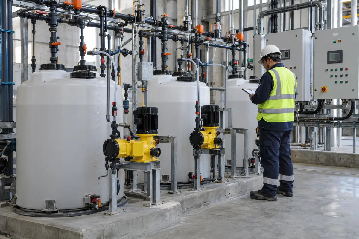
This kind of staged approach is what I mean when I say brine treatment is a system, not a piece of equipment. If you’re planning a similar project, looking at how electroplating wastewater treatment projects are structured can give you a useful reference for the pre-treatment and concentration stages.
Regulatory Context: What You Need to Know
Discharge rules for brine vary widely by jurisdiction and receiving water. In the U.S., the EPA’s Effluent Guidelines Program sets technology-based limits for many industrial categories, and states often layer on their own requirements. The EPA Effluent Guidelines are a good starting point for understanding what applies to your industry.
For facilities discharging to surface water, the World Bank’s Environmental, Health, and Safety Guidelines provide useful benchmarks for TDS and specific ion limits in different sectors. These aren’t regulations, but they’re widely referenced by lenders and permitting authorities.
The practical takeaway: know your discharge limit before you design anything. It’s the single biggest constraint on the technology selection.
Frequently Asked Questions
What’s the difference between MVC and MVR?
They’re essentially the same technology. MVC stands for mechanical vapor compression, MVR for mechanical vapor recompression. Both use a compressor to recompress vapor and reuse its latent heat. The terminology varies by region and vendor, but the working principle is identical.
How do I decide between membrane concentration and thermal evaporation?
Start with TDS. Below roughly 50,000 mg/L, membranes are usually more economical. Above that, thermal becomes necessary. But the real answer is often “both” — use membranes to concentrate as far as practical, then thermal to finish. The membrane stage does the cheap volume reduction; the thermal stage handles what membranes can’t.
What pre-treatment is essential for a brine evaporator?
At minimum: softening to remove calcium and magnesium, pH adjustment, and antiscalant dosing. If silica is present above 120–150 mg/L, you need a silica removal strategy. If COD is high, you need organics removal to prevent foaming. Skipping any of these will show up as fouling, foaming, or both.
How often will I need to clean the evaporator heat exchangers?
With good pre-treatment, I’d expect cleaning every 6–12 months. With poor pre-treatment, you might be cleaning monthly or more. The cleaning frequency is the best indicator of whether your pre-treatment is working. If it’s climbing, investigate the feed chemistry before you blame the evaporator.
What’s the typical energy consumption for a brine treatment system?
It depends heavily on the technology mix. A membrane-only system might use 3–10 kWh per m³. An MVC evaporator typically uses 15–40 kWh per m³ of distillate. A crystallizer can use 50–150 kWh per m³. The total for a full ZLD train is usually in the range of 30–80 kWh per m³ of feed, but this varies widely with feed chemistry and design choices.
Can I run a ZLD system without a crystallizer?
In some cases, yes. If you can achieve near-complete volume reduction in the evaporator and dispose of the concentrated brine as a liquid (to a permitted disposal well or off-site treatment facility), you may not need a crystallizer. But if the goal is truly zero liquid discharge, you need a crystallizer or spray dryer to produce a solid.
What’s the biggest mistake you see in brine treatment projects?
Underestimating pre-treatment. I’ve seen more projects fail because of inadequate softening or silica removal than for any other reason. The evaporator or membrane gets blamed, but the real problem is upstream. Fix the pre-treatment and the rest of the system usually performs as designed.
How do I handle foaming in the evaporator?
First, reduce the source — remove organics and surfactants in pre-treatment. Second, design the evaporator with adequate vapor space and a proper demister. Third, use antifoam dosing as a backup, not a primary control. If you’re relying on antifoam to keep the system running, you have a pre-treatment problem.
What maintenance tasks are most often neglected?
Trending performance data. Most plants log the basics but don’t look at trends until something fails. If you track approach temperature, compressor amps, and membrane pressure drop weekly, you’ll see problems developing weeks before they cause a shutdown. That’s the difference between planned maintenance and emergency repairs.
How long does a typical brine treatment system last?
With proper maintenance, a well-designed system can run 15–20 years. Membranes typically last 3–7 years depending on feed quality. Compressors may need overhaul every 5–8 years. Heat exchangers can last the life of the plant if scaling is controlled. The key variable is pre-treatment quality — it determines how hard the rest of the system has to work.