

If you’re specifying equipment for a semiconductor fab’s wastewater plant, the short answer is this: no single machine handles the whole stream. The best wastewater treatment equipment for semiconductor industry applications is a staged train — separate pretreatment for fluoride and metals, biological treatment for organics and nitrogen, membrane concentration for high-TDS streams, and evaporation or crystallization for the final brine. What you actually buy depends on which waste streams you generate, how tight your discharge limits are, and whether your site has room for a ZLD block. Below I’ll walk through the equipment I’ve seen work reliably, where each unit fits, and the trade-offs that decide the selection.
What Makes Semiconductor Wastewater Different
I’ve commissioned systems for fabs and for the chemical suppliers that feed them, and the wastewater always surprises people who come from municipal or general industrial backgrounds. The flow is relatively small compared to a steel mill or a refinery, but the chemistry is brutal and it changes fast.
A typical fab sends out several distinct streams that should never be mixed at the source:
- Fluoride-bearing streams from wafer etching and cleaning — low pH, aggressive, and expensive to treat if it reaches the biological stage.
- Copper and other metal streams from CMP (chemical mechanical planarization) and plating lines.
- Ammonia and ammonium from certain wet-clean and deposition steps — this is often the single hardest parameter to meet.
- Organic-laden streams carrying solvents, photoresist residues, and surfactants.
- High-TDS and brine streams from ion exchange regeneration, reverse osmosis concentrate, and scrubber blowdown.
Mix them all in one sump and you’ve created a problem no single piece of equipment can solve. Segregation at the source is the first equipment decision, and it’s made before you buy anything.
Stage 1: Fluoride and Heavy Metal Pretreatment
Fluoride removal is almost always the first chemical step. The standard approach is two-stage calcium precipitation: lime or calcium chloride to drop fluoride as calcium fluoride, then a polishing dose of alum or a rare-earth coagulant to push residual fluoride down to the low single digits in mg/L. I’ve seen this done in conventional clarifiers and in compact high-rate clarifiers, and the choice usually comes down to footprint.
Heavy metals come out the same way — hydroxide precipitation at the right pH window for each metal, then flocculation and settling. Where the metals are chelated (common with some CMP slurries), you’ll need a chelate-breaking step first, or the precipitation simply won’t work. This is one of the most common reasons a new metals system fails its first performance test.
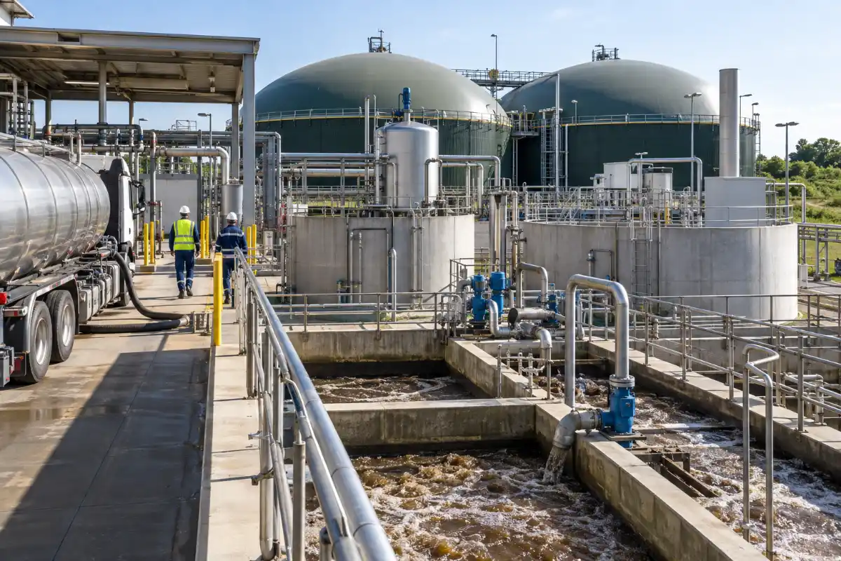
Equipment here is straightforward but must be corrosion-resistant. FRP, PP, or lined carbon steel for tanks; pH and ORP control loops with redundant probes; and a sludge handling train that doesn’t clog. For the sludge side, a screw press dewatering unit is a solid choice for metal hydroxide sludge because it runs continuously, tolerates variable feed, and needs less operator attention than a filter press.
Stage 2: Biological Treatment for Organics and Nitrogen
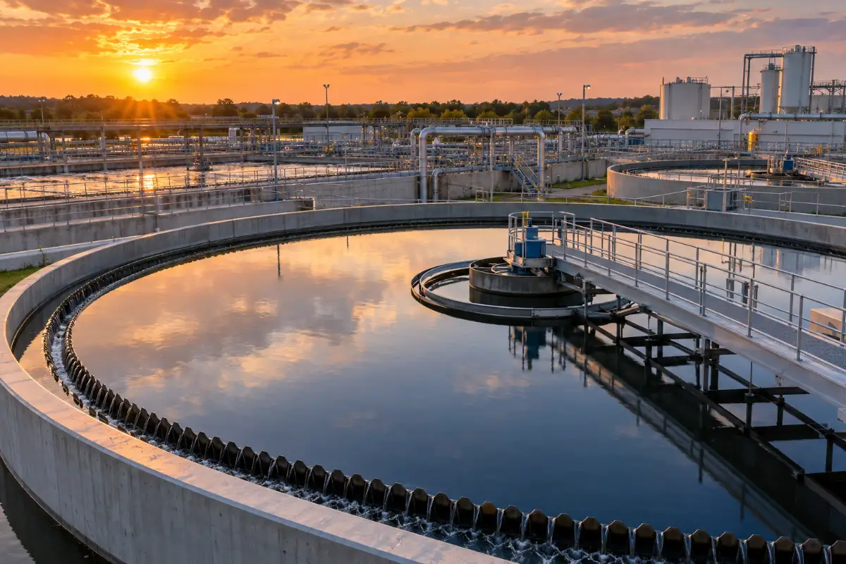
Once metals and fluoride are out, the remaining stream is mostly amenable to biological treatment. The challenge in semiconductor wastewater is the carbon-to-nitrogen ratio — you often have far more nitrogen than carbon, which starves conventional denitrification.
Options I’ve used successfully:
- MBBR (moving bed biofilm reactor) for nitrification when the flow is variable and you want biomass that won’t wash out.
- MBR (membrane bioreactor) when you need a small footprint and consistent effluent quality — the membrane replaces the clarifier and holds solids tightly.
- Conventional activated sludge with external carbon dosing when you have space and can tolerate the chemical cost.
Ammonia removal is where most designs get tested. If your permit limit is aggressive, plan for a dedicated nitrification stage with enough alkalinity and dissolved oxygen, and don’t assume a single aeration basin will do both carbon and nitrogen well at the same time.
Stage 3: Membrane Concentration
After biological treatment, you’re usually left with a stream that’s clean enough to discharge but too saline to reuse, or a reject stream that needs further concentration before evaporation. This is where membrane systems earn their place.
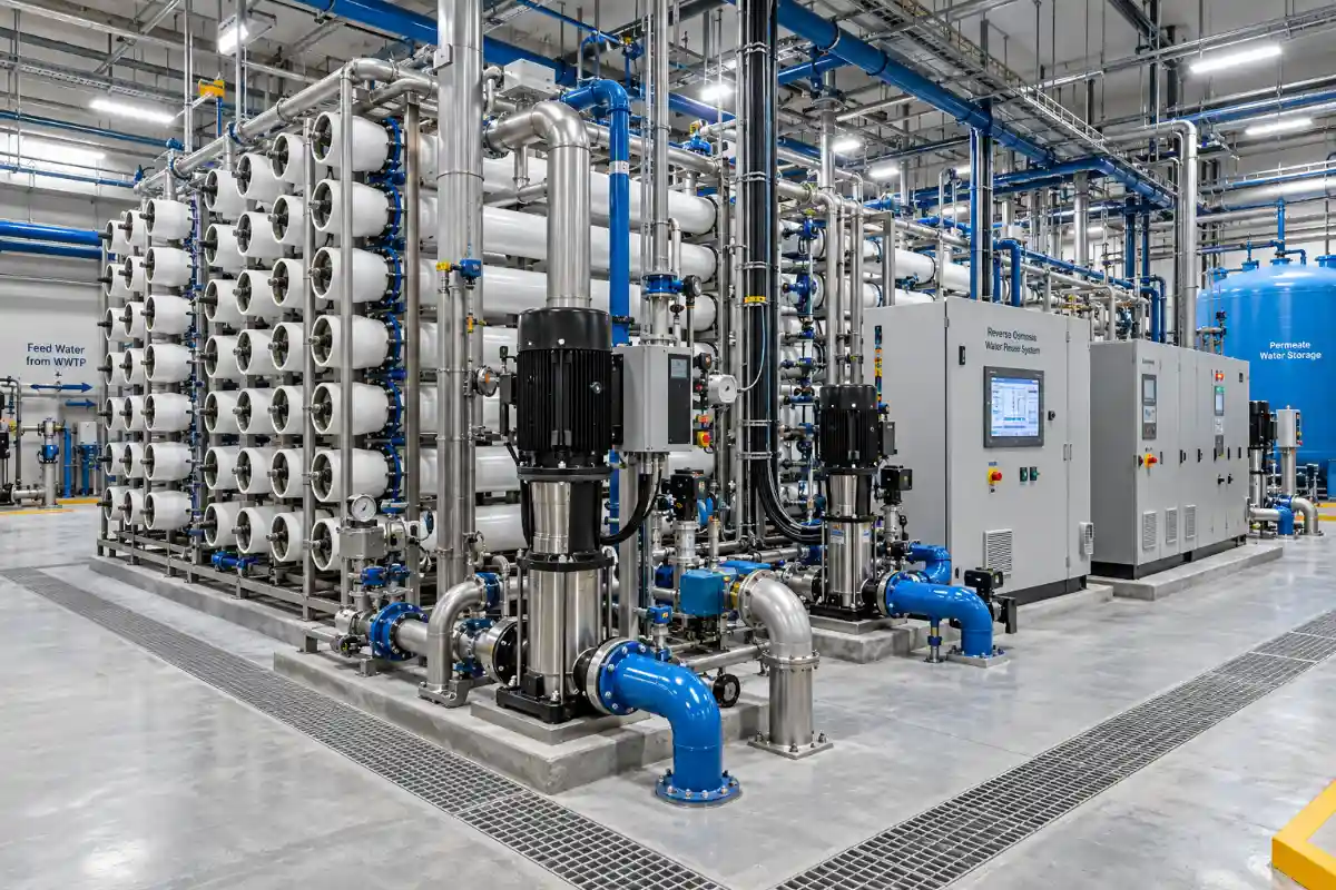
For moderate salinity, a standard industrial RO skid does the job. For high-salinity or high-fouling streams — RO concentrate, scrubber blowdown, streams with high silica or scaling potential — a DTRO membrane system handles conditions that would foul a conventional spiral-wound element. DTRO’s open-channel design tolerates suspended solids and scaling better, and it’s often the bridge between biological effluent and an evaporator.
A word of caution from experience: membrane selection is driven by the fouling index and the scaling chemistry, not by the nominal salt concentration. I’ve seen projects pick the wrong membrane because they only looked at TDS and ignored silica. Get a proper water analysis and a pilot if the stream is unusual.
Stage 4: Evaporation and Concentration
When you need to shrink the volume of a brine stream, evaporation is the workhorse. The choice between technologies is mostly about energy cost, steam availability, and how much concentration you need.
| Technology | Best Fit | Energy Character | Typical Use in a Fab |
|---|---|---|---|
| MVC (mechanical vapor compression) | Moderate flows, electricity available, no cheap steam | Electric compressor drives the heat cycle; low specific energy per unit of water evaporated | Concentrating RO reject and mixed brine |
| MVR (mechanical vapor recompression) | Similar to MVC, often used interchangeably in project specs | Recovers latent heat via recompression; strong OPEX profile | Brine concentration before crystallization |
| Multi-effect evaporation | Steam is available and cheap; larger flows | Thermal, staged across effects to reuse heat | High-volume concentration duty |
| Crystallization | ZLD requirement; solids must leave as salt | Highest energy per unit; usually the last stage | Final brine disposal as solid |
In my experience, the MVC versus MVR decision usually comes down to site utilities and how the vendor defines the boundary. Functionally they’re both mechanical vapor recompression cycles, and the MVR technology discussion is really about compressor type, heat exchanger design, and how well the system handles scaling. If you have cheap waste steam, multi-effect evaporation can beat both on operating cost. If you don’t, mechanical compression wins.
The heat exchanger is where these systems live or die. Scaling on the evaporator surfaces is the number one reliability problem I see, and it’s why heat exchanger design and material selection deserve more attention than they usually get in the bid stage.
Stage 5: Zero Liquid Discharge — When You Actually Need It
ZLD is not a default. It’s a decision driven by permit limits, water scarcity, and corporate sustainability targets. Where it’s required, the train typically looks like: pretreatment → biological → membrane concentration → evaporator → crystallizer. The output is distillate you can reuse and a dry salt cake for off-site disposal.
The cost profile is steep, and most of it is energy and maintenance, not capital. A ZLD system that isn’t properly designed for your specific brine chemistry will spend more time down for cleaning than running. Before committing, model the scaling ions carefully and consider whether you can meet the permit with partial ZLD instead — concentrate the brine, dispose of a small volume of liquid, and skip the crystallizer.
Engineering note: I’ve seen more ZLD projects fail on scaling chemistry than on any mechanical issue. Design the pretreatment to remove scale-forming ions before they reach the evaporator, and the whole train gets easier.
How to Choose: A Practical Selection Framework
When I help a fab or an EPC contractor narrow down equipment, we work through these questions in order:
- What are the actual discharge limits? Not the design guideline — the permit. This sets the required removal efficiency and tells you whether ZLD is on the table.
- What streams can be segregated? Segregation reduces treatment cost more than any equipment upgrade.
- What utilities are available? Steam, electricity price, cooling water, and available footprint all shape the technology choice.
- What’s the fouling and scaling risk? This decides membrane type and evaporator configuration.
- What’s the maintenance philosophy? A system that needs daily cleaning is a bad fit for a fab running 24/7 with a lean utility crew.
- What’s the lifecycle cost, not the capex? Energy and consumables usually dominate over a 10-year horizon.
Energy and Lifecycle Cost: Where the Money Goes
For a semiconductor wastewater plant, the operating cost split typically looks like this:
- Evaporation and crystallization: the largest energy consumer by far, if present.
- Biological aeration: significant and continuous, driven by blower efficiency and DO control.
- Chemical dosing: lime, coagulants, polymers, and external carbon for denitrification.
- Membrane replacement: periodic but predictable; DTRO and RO elements have known service lives.
- Sludge and salt disposal: often underestimated at the design stage.
The single biggest lever on OPEX is usually the evaporator. A well-designed mechanical compression system can cut evaporation energy substantially compared to a once-through thermal design, but only if the heat exchanger stays clean. That’s why I push clients to invest in proper pretreatment and automated cleaning rather than shaving capex on the front end.
If you’re at the stage where you’re comparing configurations and want a second opinion on the train, it’s worth a conversation before the equipment is locked in. Talk through your stream data with an engineer — the earlier that happens, the more money it saves.
Maintenance and Common Failure Points
After enough commissioning and troubleshooting, the failure patterns become predictable:
Scaling in evaporators and heat exchangers
Cause: inadequate pretreatment of calcium, silica, or sulfate. Fix: soften or remove scale-forming ions upstream, and design for periodic chemical cleaning with a defined CIP procedure.
Membrane fouling and flux decline
Cause: organics, colloidal silica, or biological growth on the membrane surface. Fix: better upstream removal, appropriate antiscalant dosing, and a cleaning regime matched to the foulant.
Poor nitrification in biological stages
Cause: low alkalinity, low dissolved oxygen, or cold temperatures. Fix: alkalinity supplementation, DO control, and possibly a larger or staged reactor.
Sludge dewatering underperformance
Cause: wrong polymer, variable feed solids, or a press that’s undersized for peak load. Fix: polymer jar testing, equalization ahead of the dewatering unit, and honest peak-flow sizing.
Corrosion in fluoride and acid streams
Cause: material selection based on nominal conditions rather than worst-case pH and temperature. Fix: specify materials with margin and inspect during commissioning.
Equipment Summary Table
| Treatment Goal | Equipment | Key Selection Driver |
|---|---|---|
| Fluoride removal | Two-stage precipitation + clarifier | Target residual, sludge handling |
| Heavy metals | Hydroxide precipitation + flocculation | Chelation, pH control |
| Organics and nitrogen | MBBR, MBR, or activated sludge | Footprint, C:N ratio, permit limit |
| Salinity reduction | Industrial RO or DTRO | Fouling index, scaling risk |
| Brine concentration | MVC / MVR or multi-effect evaporator | Steam availability, energy price |
| Final disposal | Crystallizer (ZLD) or liquid discharge | Permit, disposal cost |
| Sludge handling | Screw press or filter press | Feed variability, cake dryness target |
Lessons From the Field
A few things I’d tell anyone specifying this equipment:
Pilot before you commit on anything unusual. Bench and pilot data on your actual stream will save you from a wrong membrane or a scaling evaporator. Vendors quote on generic water; your water isn’t generic.
Design for turndown. Fabs ramp production, and a system sized for peak flow runs badly at half load. Ask how the equipment performs across the expected range, not just at design point.
Don’t underestimate the sludge and salt side. The treatment train gets all the attention, but the solids handling is what determines whether operators are happy three years in.
And get the segregation right at the source. It’s the cheapest treatment step you’ll ever build, and it’s the one most often skipped in the rush to order equipment.
FAQ
What is the most important piece of equipment in a semiconductor wastewater plant?
There isn’t one. The pretreatment stage — fluoride and metals removal — protects everything downstream, so it’s arguably the most critical. But a plant with excellent pretreatment and a poorly designed evaporator still fails. Treat it as a train where each stage depends on the one before it.
Is ZLD always required for semiconductor wastewater?
No. ZLD is driven by permit limits, water scarcity, and corporate targets. Many fabs meet their permits with conventional treatment plus membrane concentration and discharge a small volume of brine. Partial ZLD is often the better economic choice.
How do I choose between MVC and multi-effect evaporation?
Look at your steam and electricity costs. If you have cheap or waste steam, multi-effect evaporation can have lower operating cost. If electricity is your main utility and steam is expensive or unavailable, mechanical vapor compression usually wins. Flow rate and required concentration also matter.
How often do membranes need replacement?
It depends heavily on the stream and the cleaning regime. RO and DTRO elements typically last several years with good pretreatment and regular cleaning, but aggressive or fouling streams shorten that. Budget for replacement as a recurring cost, not a one-time purchase.
What causes an evaporator to scale, and how do I prevent it?
Calcium, silica, sulfate, and carbonate are the usual culprits. Prevention starts upstream: soften or remove scale-forming ions before they reach the evaporator. Also design for chemical cleaning with a defined procedure, and monitor the heat transfer coefficient so you catch fouling early.
Can I reuse the distillate from an evaporator?
Often yes, depending on quality requirements. Evaporator distillate is usually low in dissolved solids and can be polished further for reuse in cooling or certain process steps. Verify the quality against your reuse specification before committing.
What’s the biggest mistake in specifying this equipment?
Sizing on average flow and generic water quality. Real fabs have variable flows, variable chemistry, and peak loads. Design for the range, pilot the unusual streams, and don’t cut corners on the solids handling side.
If your project is at the selection stage, the most valuable thing you can do is get real water data and talk through the train with someone who has commissioned one. That conversation costs nothing and often changes the equipment list before it’s too late to matter.