

Chemical plant wastewater is rarely a single stream. In most facilities I walk through, it is a moving target: brine from ion exchange regeneration on Monday, spent caustic on Tuesday, wash water with trace solvents on Wednesday. A concentration system is what lets you shrink that volume before final disposal, reuse, or zero liquid discharge. The goal is simple to state and hard to execute: remove water, keep the dissolved solids in as small a reject stream as possible, and do it without fouling, scaling, or burning through your energy budget. This article covers how I approach system selection, design margins, energy trade-offs, and the operating habits that keep these plants running.
What Makes Chemical Plant Wastewater Different
Municipal wastewater is forgiving. Chemical plant wastewater is not. Before you size any concentrator, you need a clear picture of what is actually in the stream, because the chemistry drives every downstream decision.
The parameters that matter most in my experience:
- Total dissolved solids (TDS). Anything above roughly 30,000–50,000 mg/L starts pushing reverse osmosis toward its practical limits and makes evaporation more attractive.
- Scaling ions. Calcium, magnesium, barium, strontium, silica, and sulfate. These decide whether you can concentrate at all, or whether you need softening, antiscalant, or seeding.
- Organics and oils. Even a few hundred mg/L of oil can destroy heat transfer surfaces and foul membranes. Organics also drive foaming in evaporators.
- Volatile compounds. Solvents, ammonia, and light organics can carry over into condensate, which then needs its own treatment.
- pH and corrosivity. Chlorides plus low pH means you are choosing between titanium, duplex stainless, and exotic alloys.
- Temperature. Hot streams can be an advantage for evaporation, but they can also stress membrane materials.
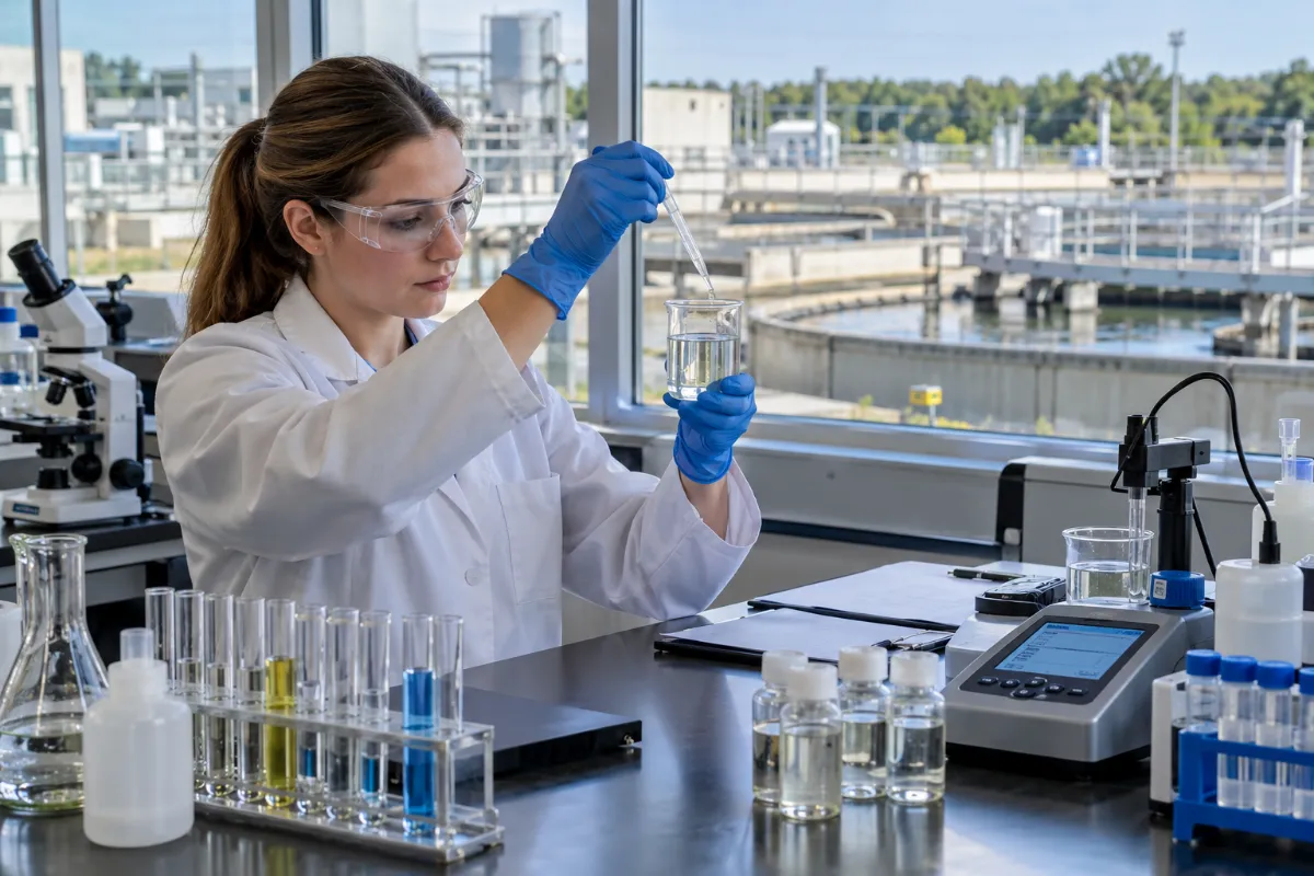
I always ask for at least three months of analytical history, not a single grab sample. Chemical plants swing. A design based on one good day will fail on a bad week.
Choosing Between Membrane Concentration and Evaporation
The first real decision is whether you concentrate with membranes, with heat, or with both in series. This is where most project budgets are won or lost.
When Membranes Make Sense
Membrane concentration is the lower-energy option when your feed is compatible. A high-pressure RO system can push brine to 70,000–90,000 mg/L TDS in the right conditions, and disc-tube style DTRO membrane systems handle higher fouling feeds than spiral-wound elements. The trade-off is pretreatment: any membrane at high concentration is sensitive to scaling and organic fouling. If your feed has high hardness or silica, you will spend the savings on softening and cleaning.
When Evaporation Wins
Once TDS climbs past the membrane ceiling, or when the stream is oily, scaling-prone, or contains solvents, thermal concentration takes over. Evaporators are robust, but energy is the whole story. A mechanical vapor compression MVC evaporator reuses its own vapor and typically lands in the 15–50 kWh per cubic meter of distillate range for well-designed units, depending on boiling point elevation and compressor efficiency. A multi-effect evaporator cuts steam consumption by reusing heat across stages, but it needs a steam supply and more plot space.
In many chemical plants, the practical answer is a hybrid: membrane pre-concentration followed by evaporation of the membrane reject. You shrink the evaporator, cut its energy load, and keep the membrane in the range where it behaves.
Comparing Concentration Technologies Side by Side
The table below reflects typical design ranges I use for early-stage screening. Actual numbers depend on your feed chemistry, required concentration factor, utility costs, and site constraints.
| Technology | Typical Feed TDS Range | Energy Profile | Best Fit | Main Risk |
|---|---|---|---|---|
| Industrial RO | Up to ~40,000 mg/L | Low (3–8 kWh/m³) | Low-salinity, clean feeds | Scaling, organic fouling |
| High-pressure RO / DTRO | 40,000–90,000 mg/L | Moderate (8–15 kWh/m³) | Brackish brines, landfill leachate | Concentrate management |
| MVC evaporator | 30,000–250,000 mg/L | Moderate (15–50 kWh/m³ distillate) | Most chemical brines | Compressor maintenance, scaling |
| Multi-effect evaporator | 30,000–300,000 mg/L | Low electrical, high steam | Sites with cheap steam | Steam cost, larger footprint |
| MVR evaporator | 30,000–300,000 mg/L | Electrical, no steam | Steam-limited sites | Compressor CAPEX |
| Crystallizer (ZLD) | Above 250,000 mg/L | High | Zero liquid discharge targets | Solid handling, salt purity |
These are indicative ranges, not guarantees. A stream with 60,000 mg/L TDS and 200 mg/L silica behaves very differently from a clean 60,000 mg/L NaCl brine, and the design follows the chemistry, not the number.
Design Margins That Save You Later
The single most common mistake I see in chemical plant concentration projects is designing to the average. Plants do not run at average.
A few margins I build in as standard:
- Flow margin: 15–25% above the expected peak, because production campaigns and cleaning cycles both spike flow.
- Concentration margin: Design the evaporator to reach a slightly higher solids concentration than the target, so you can operate below the limit and still hit spec.
- Heat transfer margin: 10–20% extra surface area is cheap compared to a re-tube.
- Antifoam and cleaning provisions: Assume you will need them. Foaming in evaporators is not an exception; it is a Tuesday.
- Turn-down capability: Chemical plants run at 40% capacity sometimes. Your concentrator should too.
Energy, Cost, and the Lifecycle View
Operating cost in a concentration system is dominated by two things: electricity for compressors and pumps, and steam where it is used. Capital cost is dominated by materials of construction and the compressor.
What I tell clients when they ask about payback:
“Do not compare equipment prices. Compare the cost per cubic meter of water removed over ten years, including cleaning chemicals, membrane or heat exchanger replacement, compressor overhaul, and the labor to run it. That number is the only one that matters.”
Some rough planning figures I use, clearly labeled as project-dependent:
- MVC evaporator electrical demand: roughly 15–50 kWh per m³ of distillate.
- Multi-effect evaporator steam demand: roughly 0.3–0.5 kg steam per kg of water evaporated for a three-effect unit, less for more effects.
- Membrane replacement: every 3–7 years depending on feed and cleaning discipline.
- Compressor overhaul: every 3–5 years on MVC and MVR units.
If your site has waste heat or cheap steam, multi-effect designs usually win on operating cost. If steam is unavailable or expensive, MVC or MVR is the better fit. For a deeper look at how MVR compares, the MVR evaporator overview is a reasonable starting point.
Pretreatment: The Part Everyone Underestimates
Every concentration system has a pretreatment train in front of it, whether the designer admits it or not. Skipping or shrinking pretreatment is the fastest way to turn a clean design into a maintenance nightmare.
Typical pretreatment steps for chemical plant feeds:
- Equalization. Buffer flow and chemistry swings. Size for at least 8–12 hours of average flow.
- Oil and grease removal. Dissolved air flotation or coalescing separators, depending on the oil form.
- Chemical softening or precipitation. Remove hardness and silica before they reach heat exchangers or membranes.
- Filtration. Multimedia, cartridge, or ultrafiltration, matched to the downstream technology.
- pH adjustment. Both for scaling control and for material compatibility.
For oily feeds, the evaporation step itself needs special attention. Evaporation with oily wastewater is a different design problem than clean brine, and the heat exchanger and vapor path both change.
Operating and Maintenance Habits That Actually Matter
I have seen identical systems run for fifteen years at one plant and fail in three at another. The difference is almost always operating discipline, not equipment quality.
Daily
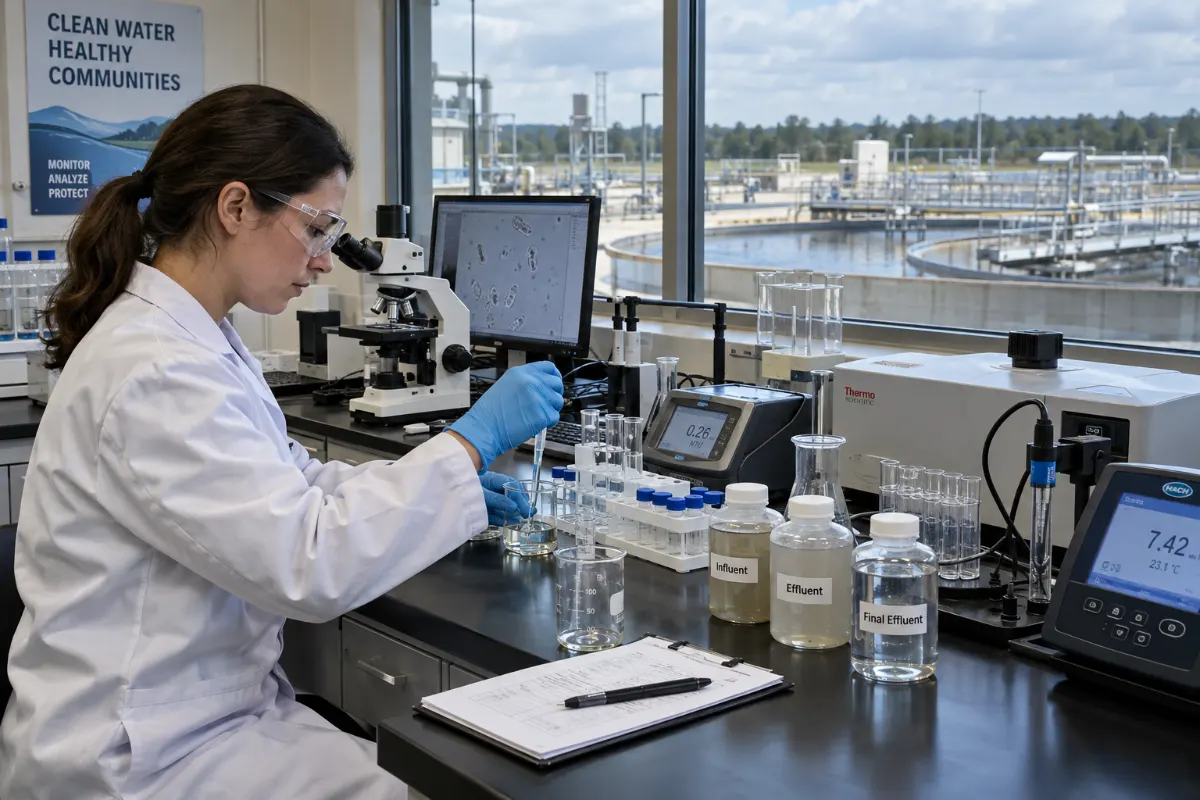
- Log feed flow, TDS, pH, and temperature. Trends catch problems before alarms do.
- Check compressor suction and discharge pressures on MVC and MVR units.
- Verify antifoam dosing and condensate quality.
Weekly
- Inspect heat exchanger surfaces through sight glasses or by differential pressure.
- Check cleaning chemical inventory and prepare for the next wash cycle.
- Review scaling indicators: conductivity, pressure drop, and boiling point elevation.
Quarterly to Annually
- Compressor oil analysis and vibration checks.
- Heat exchanger inspection and, where needed, hydro-cleaning or chemical cleaning.
- Membrane performance testing if membranes are in the train.
- Review of the actual feed chemistry against the design basis. Chemistry drifts. Your design basis should not.
Common Failure Modes and How to Avoid Them
Most failures I investigate fall into a handful of categories:
- Scaling in the heat exchanger. Usually caused by inadequate softening or antiscalant control. Fix the chemistry, not just the cleaning schedule.
- Foaming and carryover. Often tied to organics or surfactants. Antifoam helps, but reducing the source is better.
- Compressor damage. Typically from liquid carryover or from running outside the design curve. Protect the compressor with proper demisters and controls.
- Corrosion. Wrong alloy for the chloride and pH profile. This is a design error, not an operating one.
- Fouling of membranes. Almost always a pretreatment gap. Biofouling, organic fouling, and scaling each need a different response.
- Insufficient turndown. Plant runs at half rate, system cannot, and the operators improvise. Design for the range.
When a system fails repeatedly, the answer is rarely a bigger cleaning budget. It is almost always a design or pretreatment correction upstream.
Where Zero Liquid Discharge Fits
Some chemical plants face discharge limits that make any liquid reject stream unacceptable. In that case, the concentration system feeds a crystallizer and the plant moves toward zero liquid discharge. ZLD is achievable, but it is expensive in both capital and energy, and the solid salt you produce still needs a home. I always push clients to first ask whether the discharge limit truly requires ZLD, or whether a smaller, well-treated reject stream would satisfy the permit. Reducing volume before ZLD is almost always cheaper than building ZLD for the full flow.
Putting It Together: A Practical Selection Sequence
When I sit down with a chemical plant to scope a concentration system, the sequence looks like this:
- Characterize the feed thoroughly. Three months of data minimum.
- Define the target: what concentration, what final volume, what quality for reuse or discharge.
- Screen technologies against the chemistry. Membranes first if compatible, evaporation if not, hybrid if both.
- Size with margins for flow, concentration, and heat transfer.
- Design pretreatment to protect the concentration step.
- Model operating cost over ten years, not first cost.
- Plan the maintenance program before commissioning, not after the first failure.
If you want a second opinion on a specific stream or an existing system that is underperforming, our engineering team reviews feed data and proposes a configuration. You can start a project conversation here.
Frequently Asked Questions
How do I know if I need evaporation or just high-pressure RO?
Start with your target concentration and your scaling potential. If you need to go above roughly 70,000–90,000 mg/L TDS, or if your feed has high hardness, silica, or oils, evaporation is usually the more reliable path. If your feed is relatively clean and your target is moderate, high-pressure RO or DTRO can handle it at much lower energy cost. A hybrid often gives the best balance.
What is a realistic energy consumption for an MVC evaporator?
For well-designed units on typical chemical brines, plan on roughly 15–50 kWh per cubic meter of distillate. The number moves with boiling point elevation, compressor efficiency, and how close to saturation you concentrate. Streams with high salt content and high boiling point elevation sit at the upper end.
How often will I need to clean the heat exchangers?
With good pretreatment and antiscalant control, many plants clean every three to six months. Without them, monthly or more. The cleaning frequency is a direct indicator of whether your pretreatment is doing its job.
Can I concentrate a stream that contains oil?
Yes, but with a different design. Oily feeds need oil removal upstream, and the evaporator itself needs a heat exchanger and vapor path that resist organic fouling. Foaming control is also more demanding. Trying to run an oily feed through a standard clean-brine design is a common and expensive mistake.
What is the biggest cause of premature compressor failure in MVC systems?
Liquid carryover. When droplets reach the compressor, they cause erosion and imbalance. Proper demister design, correct liquid level control, and a well-tuned startup sequence prevent most of these failures. Vibration monitoring catches the rest before they become catastrophic.
Is zero liquid discharge always the right answer?
No. ZLD is energy-intensive and produces solid waste that still needs disposal. It is the right answer when discharge limits or site constraints leave no other option. In most cases, reducing volume through concentration and treating a small reject stream is more cost-effective than full ZLD.
How much feed data do I need before designing a system?
At minimum, three months of analytical history covering the full range of production campaigns. A single grab sample is not enough. If your plant runs seasonal or campaign-based production, you need data from each campaign, because the worst-case stream drives the design.